H. switching frequency across dim range, An368 – Cirrus Logic AN368 User Manual
Page 23
AN368
AN368REV2
23
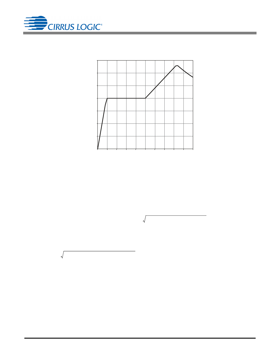
h. Switching Frequency Across Dim Range
From the equations below and setting the OTP registers as follows, the switching frequency across the dim
range can be calculated. A sample plot of the switching frequency across dim values is shown in Figure 7.
The frequencies in regions A, B, C, and D are governed by Equations 44, 45, 46 and 47, respectively.
Transitions between connecting regions are the result of simple inequalities. The following four equations do
not include the effect of a color system. Equations 44 through 47 must be adjusted after the color system has
been designed.
Frequency in Region A
In Region A, the system operates in CRM, and the period TT
A
is calculated using Equation 44:
where,
TT
A
> TT
B
at the given dim level
dim = The 12-bit dim level provided by the boost stage
Frequency in Region B
In Region B, the system operates in DCM, but the peak current remains the same. Period TT
B
is calculated
using Equation 45:
where,
TT
B
< 50
s
TT
B
> TT
A
0
5
10
15
20
25
30
35
0.10
0.20
0.30
0.40
0.50
0.60
0.70
0.80
0.90
1.00
Frequency (kHz
)
Dim
D
C
B
A
Figure 7. Dual Pulses Switching Frequency
TT
A
0.5
TT
dim1
TT
dim2
+
TT
dim1
TT
dim2
+
2
4 T
res
+
+
2
=
[Eq. 44]
TT
dimx
2 L dim I
MODEx
N
2
V
MODEx
1 D
MODEx
–
=
[Eq. 45]
TT
B
TT
FREQ
dim
--------------------
=