I. calculate r, J. calculate flyback zero-current detection, An368 – Cirrus Logic AN368 User Manual
Page 18
AN368
18
AN368REV2
The RMS current in the secondary winding I
SEC(RMS)
is calculated using Equation 30:
i. Calculate R
Sense
(R21)
A scaling factor is used to provide for a margin to account for manufacturing tolerances of external
components, such as inductance and resistance tolerance. Calculate sense resistor R
Sense
(R21) for flyback
using Equation 31:
where,
f
scale
= Scaling factor
R21 = R
Sense
in
Calculate the power P
Sense
dissipated by the sense resistor R
Sense
(R21) using Equation 32:
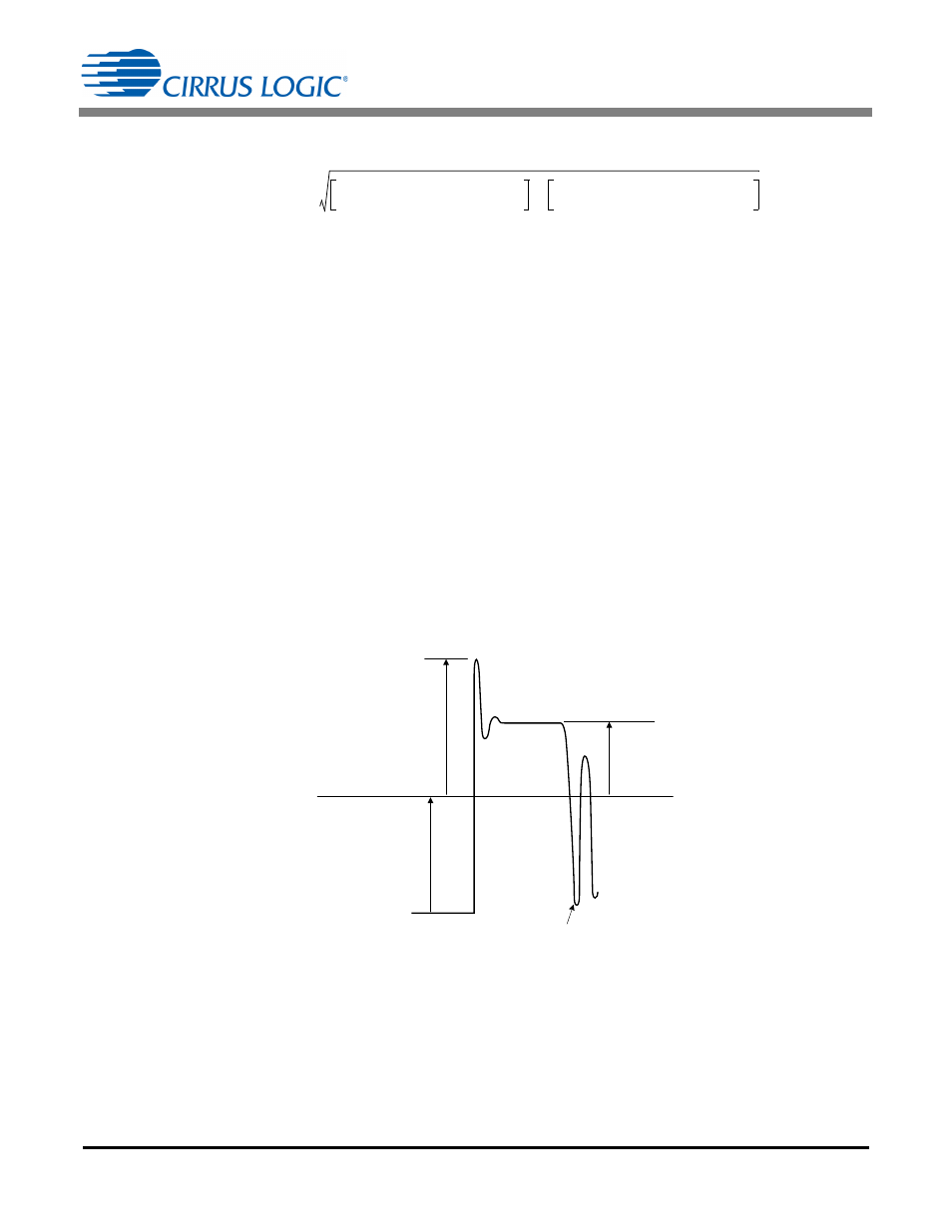
j. Calculate Flyback Zero-current Detection
The CS1630 uses zero-current detection (ZCD) to minimize switching losses. The ZCD algorithm is designed
to turn ‘ON’ the flyback FET Q5 when the resonant voltage across the FET is at a low point (see Figure 5).
Valley switching reduces the CV
2
power losses associated with the body capacitance of the FET. Pin FBAUX
is designed to monitor the resonant voltage from the auxiliary winding of the flyback transformer T1.
The auxiliary turns ratio must be designed such that the output voltage from the auxiliary winding is attenuated
by a resistor voltage divider that results in a 1.25V input to the FBAUX pin when the OVP threshold V
OVP
is
reached. In addition, the total current through the ZCD circuit should be limited to less than 1mA. The
transformer TX1 auxiliary winding turns ratio
is calculated using Equation 33:
[Eq. 30]
I
SEC RMS
N
2
I
PK1 FB
2
1 D
MODE1
–
3
-----------------------------
N
2
I
PK2 FB
2
1 D
MODE2
–
3
-----------------------------
+
=
[Eq. 31]
R
Sense
1.4V
f
scale
I
PK1 FB
-------------------------------------
=
[Eq. 32]
P
Sense
I
PRI RMS
2
R
Sense
=
First Valley
Flyback FET
Voltage
V
CLAMP
V
BST
V
Reflected
Figure 5. Switching Waveform of Flyback FET Drain
[Eq. 33]
N
P
N
FBAUX
-------------------
2 N V
OVP
R23
1.25V
R22 R23
+
------------------------------------------------------
=