An368 – Cirrus Logic AN368 User Manual
Page 39
AN368
AN368REV2
39
The frequency range should be as high as possible without exceeding 75kHz. This strategy keeps the
fundamental and second harmonic below the 150kHz EMI requirements.
In most low-power designs, the boost inductor peak current I
PK(BST)
is much higher than the RMS value.
Specify the boost inductor turns such that the core reaches 3000Gauss when the current equals 600mA. To
protect against runaway, set the artificial load to a constant voltage to achieve nominal
V
BST
, then adjust the
value of R
IPK
to obtain nominal boost output current I
BST(nominal)
.
Measure the switching frequency in the high current region in the 45° to 90° AC phase angle range. Adjust the
boost inductor value to determine the desired frequency. Adjustments to the inductor value are made by
changing the gap. Increasing the gap is always safe, but reducing the gap may saturate the core. It may be
beneficial to redesign the boost inductor if changes to the inductor gap are greater than 20%.
0
10
20
30
40
50
60
70
80
90
100
110
120
130
140
10
20
30
40
50
60
70
80
90
100
110
120
130
140
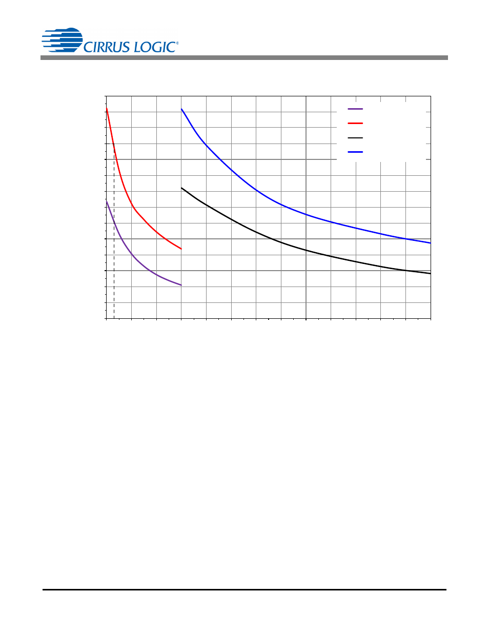
120V Min Freq
120V Max Freq
230V Min Freq
230V Max Freq
Power Multiplied by Inductance (Watts Multiplied by mH)
Sw
itching Frequency
(kHz
)
Figure 19. Switching Frequency vs Power Multiplied by
Inductance