Hpv removal and replacement - c & d pumphead style – Pulsafeeder Pulsar Shadow User Manual
Page 29
23
12. Make certain that the diagnostics seal at the top of the eccentric box flange and the HPV feed port o-
ring at the bottom of the flange are in place (refer to Figure 4).
13. Insert the pumphead into the eccentric box using the locating pins as a guide.
14. Some compression of the piston return spring will be required in order to start the pumphead retaining
bolts after which the bolts can be tightened to complete installation of the head. Spring compression
will be minimized with the eccentric in the retracted position and the stroke setting at 100%.
15. Reinstall the diaphragm and reagent head.
16. Re-install the eccentric box drain plug and fill with PULSAlube 7H hydraulic oil.
17. Re-prime the pump.
7.4.4
HPV Removal and Replacement - C & D Pumphead Style
Use the following procedure for a HPV Removal and Replacement (C & D Pumphead Style)
1. Remove the reagent head and diaphragm.
2. Drain hydraulic fluid from the eccentric box.
3. Remove the four bolts on the front eccentric box flange which retain the pumphead. the piston return
spring is under compression and should force the pumphead/cylinder away from the eccentric box as
the bolts are removed. If the cylinder separates from the pumphead, remaining in the eccentric box, it
may be necessary to remove the eccentric box cover and tap out the cylinder from behind.
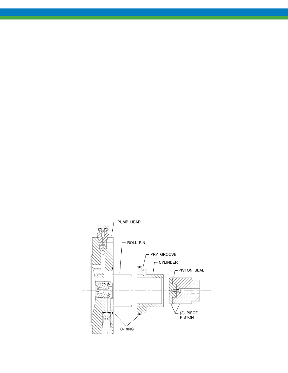
4. The cylinder is retained to the pumphead by two roll pins. Separate the cylinder by prying on the
groove above the o-ring (refer to Figure 19).
5. Using a hex wrench, unscrew the HPV from the cylinder side of the pumphead.
6. If cleaning of the valve is required, use a solvent compatible with nitrile seals and blow air through
the valve to remove all contaminants.
7. Lubricate the o-rings with PULSAlube 7H and carefully insert the HPV into the back of the
pumphead, make certain that the threads are properly engaged before tightening.
8. Align the roll pins to the appropriate holes and press the cylinder onto the pumphead, make certain
that the o-ring on the back side of the pumphead is in place
Figure 19