A125, Assembly & installation instructions – Hubbardton Forge 126503 User Manual
Page 2
If you need further assistance, or find that you are missing any parts, please contact the dealer from which you purchased this product.
We hope you enjoy your fixture!
* Hubbardton Forge will not be liable for injury or damage caused by improper installation, lamping or use of this fixture.
H U B B A R D T O N F O R G E . C O M
hand-forged, vermont-made lighting and accessories
154 RT. 30 SOUTH
•
CASTLETON, VERMONT 05735
All designs and images ©1989-2013 Hubbardton Forge
®
. All rights reserved.
19909
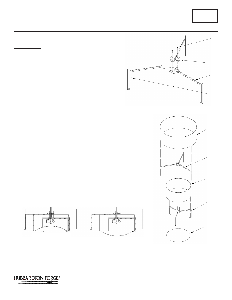
Assembly & Installation Instructions
To Assemble Outer Spider
(Figure 2)
Component Parts
F Thumb Screw (2)
G Upper Outer Arm Assembly
H Lower Outer Arm Assembly
I Outer Spider Arm
1. Assemble outer spider by placing upper outer arm assem-
bly (G) on lower outer arm assembly (H) with outer spider
arm (I) between them. Make sure outer spider arm (I) is
oriented the same as the other two arms. Slot in both
assemblies should be aligned.
2. Install (2) thumb screws (F) and tighten.
To Assemble Spider Assemblies
(Figure 3)
Component Parts
J Outer Shade
K Outer Spider
L Inner Shade
M Inner Spider
N Diffuser
1. Place inner shade (L) into notches of inner spider (M).
2. Align outer spider (K) so square openings line up with verti-
cal uprights on inner spider (M). Slots in outer spider (K)
and inner spider (L) need to align.
3. Place outer shade (J) into notches of outer spider (K).
4. Slip glass diffuser (N) curved side up at an angle into inner
spider (M) and rotate to rest on all three arms. It may be
necessary to flex on support arm slightly to install diffuser.
See Figure 3A for correct orientation of diffuser.
A125
For Exos Semi-Flush 126503
Page 2 of 3
(Figure 3)
F
(Figure 2)
G
H
J
K
L
(Continued)
I
M
N
DIFFUSER INSTALLED
CORRECTLY
DIFFUSER INSTALLED
INCORRECTLY
(Figure 3A)