A218, Assembly & installation instructions – Hubbardton Forge 137547 User Manual
Page 2
Assembly & Installation Instructions
A218
For Exos Wave Large Five Light Pendant 13-7547 & 13-7547E
Page 2 of 4
Hand-Forged,
Vermont-Made Lighting and Accessories
P.O. Box 827, 154 Route 30 South, Castleton, Vermont 05735
22897
To Install to Ceiling
(Figures 3 thru 6)
Component Parts
C Support
Cable
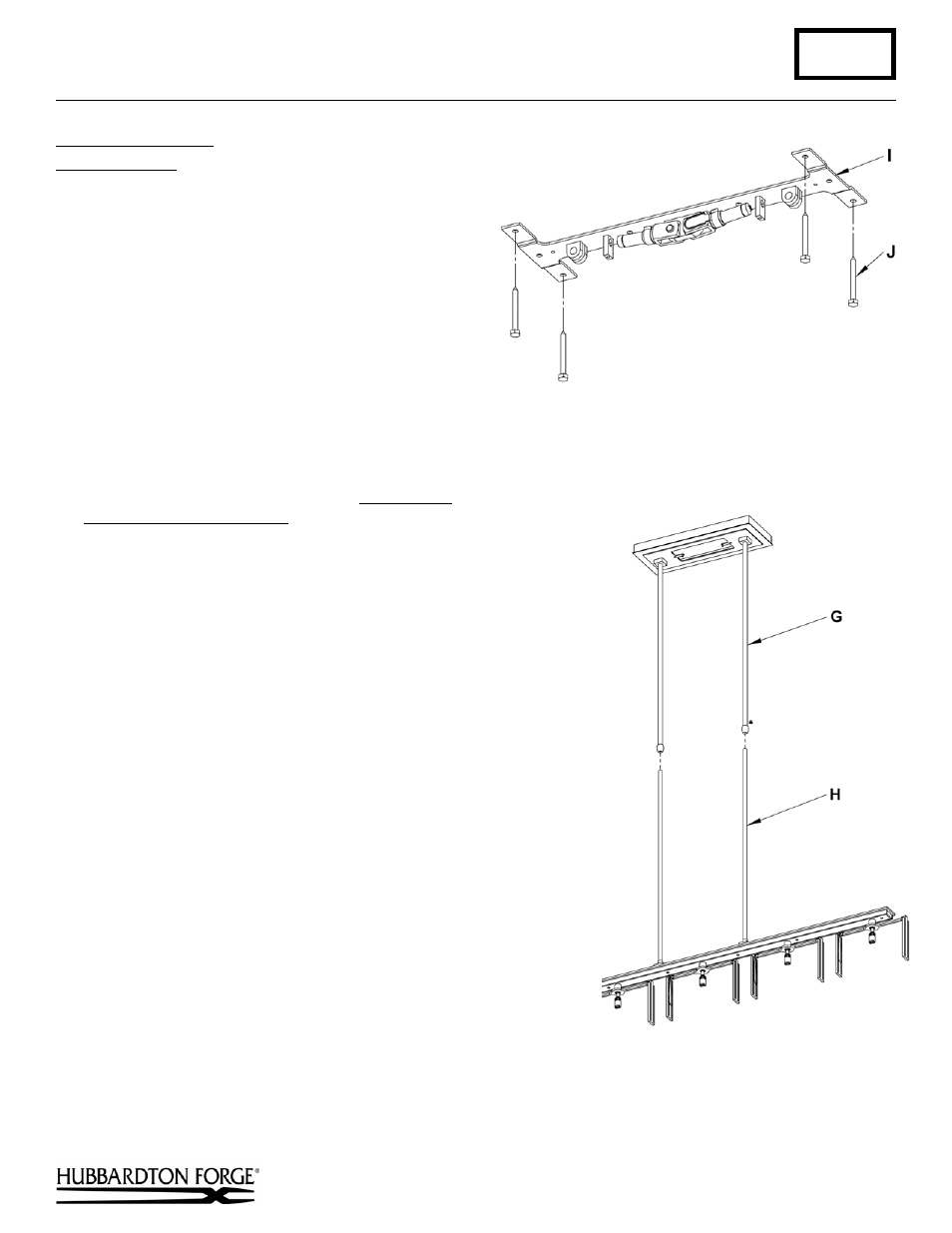
G Canopy
Assembly
H Fixture
Assembly
I Ceiling
Bracket
J Lag Screws (4)
K Cable
Gripper
L Safety
Nut
M Flat Head Screws
N Wireway
Cover
O Barrel Knobs (2)
P Ground
Screw
Q Cupped
Washer
Caution: Be sure power is off at the main breaker
box prior to
installation.
1. Using four lag screws (J) attach ceiling bracket (I)
to a structural member in the ceiling, centering the
crossbar over the outlet box. We've supplied lag screws
with your fixture; however, different materials and/or
construction methods may require different fasteners. If
in doubt, contact a qualified electrician. Do not attach
crossbar directly to outlet box (Figure 3).
2. Thread wires and support cable (C) from the fixture assembly (H)
through the canopy assembly (G) (Figure 4).
3. Loosen both safety nuts (L) on cable grippers (K). It is not
necessary to completely remove them.
4. Raise fixture and push support cables (C) into cable grippers (K)
threading them through ceiling bracket (I) as shown in Figure 5 until
cables are tight and have no slack. Push cables through grippers
until desired fixture height is accomplished.
5. Raise canopy assembly (G) to ceiling making sure the fixture pipes
and canopy pipes over lap. Fasten to ceiling bracket (I) with flat
head screws (M) (Figure 5).
6. Once support cable is at the correct height, excess cable behind the
gripper can be cut off.
7. Tighten safety nuts (L).
8. Using suitable wire connectors (not provided) connect fixture wires
to supply (white to white and black to black, and bare copper to bare
copper or green supply). Ground the ceiling bracket (I) using the
green ground screw (P) and cupped washer (Q) to secure a pigtail
lead to the bracket. Push wires back into outlet box.
Caution: Make sure wire connectors are twisted on securely, and
no bare wire is exposed.
9. Install the wireway cover (N) and secure with barrel knobs (O)
(Figure 6).
10. Refer to instructions following to install glass.
(continued)
(Figure 4)
(Figure 3)