A196, Assembly & installation instructions – Hubbardton Forge 18793 User Manual
Page 2
Assembly & Installation Instructions
A196
For Pendant 18-791 & 18-793
Page 2 of 5
Hand-Forged,
Vermont-Made Lighting and Accessories
P.O. Box 827, 154 Route 30 South, Castleton, Vermont 05735
22609
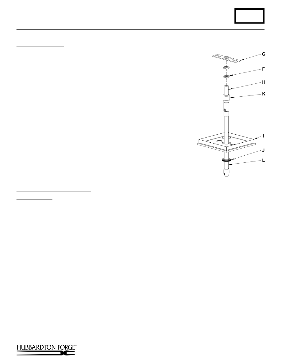
Prepare the Canopy
(Figure 3)
Component Parts
F Jam
Nuts
(2)
G Crossbar
H Threaded
Nipple
I Canopy
J Canopy
Ring
K Coupling
L Canopy
Pipe
Caution: Be sure power is off at the main breaker box prior to installation.
1. Thread Jam Nuts (F) and Crossbar (G) onto threaded nipple (H) leave both
parts loose.
2. Using two machine screws (not provided), temporarily fasten the crossbar (G)
to the electric box.
Note: A new electric box comes with screws. When
replacing a fixture, retain the existing screws for use with the new fixture.
3. Adjust the length of Threaded Nipple (H) in crossbar (G) so that Canopy Ring
(J) will hold Canopy (F) against the ceiling with no threads showing for best
appearance. When the correct adjustment is established, tighten Jam Nuts (F)
against crossbar (G) to hold the adjustment.
4. Remove the crossbar and stem from the electrical box and proceed with the
assembly instructions.
Complete Assembly and Install
(Figures 4 & 5, next page)
Component Parts
D Fixture
Pipe
F Jam
Nut
G Crossbar
H Threaded
Nipple
I Canopy
J Canopy
Ring
L Canopy
Pipe
M Plastic
Clutch
Sleeve
N Clutch
O Set
Screw
Caution: Be sure power is off at the main breaker box prior to installation.
1. Thread crossbar (G) onto threaded nipple (H) until tight against jam nuts (F).
2. Unscrew the clutch (N) from the canopy pipe (L); slide it across the wires and onto the fixture pipe (D). Follow this
with the plastic clutch sleeve (M), oriented so the tapered end of the clutch sleeve nests in the clutch (Figure 4).
3. Thread wires from the fixture pipe (D) through the canopy pipe (L).
4. Slide the canopy pipe (L) as far as necessary to give you the total length of the fixture which you desire. Be careful
not to scratch the pipe surfaces and to pull excess wire up through the canopy pipe (L). There must be a minimum 1-
1/2" of inner pipe inside the outer pipe. Screw clutch (N) onto canopy pipe and hand-tighten the clutch to
temporarily hold this adjustment. The clutch is not securely fastened at this point; do not depend on it to hold the
fixture.
Important: To ensure full connection strength, be sure the tapered end of the plastic clutch sleeve is
oriented toward the clutch when assembled and securely tighten set screw (Figure 4).
5. Using two machine screws (not provided), fasten the crossbar to the electric box.
Note: A new electric box comes with screws. When replacing a fixture, retain the existing screws for use with the
new fixture.
(continued)
(Figure 3)