A362, Assembly & installation instructions – Hubbardton Forge 137901 User Manual
Page 4
If you need further assistance, or find that you are missing any parts, please contact the dealer from which you purchased this product.
We hope you enjoy your fixture!
* Hubbardton Forge will not be liable for injury or damage caused by improper installation, lamping or use of this fixture.
H U B B A R D T O N F O R G E . C O M
hand-forged, vermont-made lighting and accessories
154 RT. 30 SOUTH
•
CASTLETON, VERMONT 05735
All designs and images ©1989-2014 Hubbardton Forge
®
. All rights reserved.
30715 Rev B
Assembly & Installation Instructions
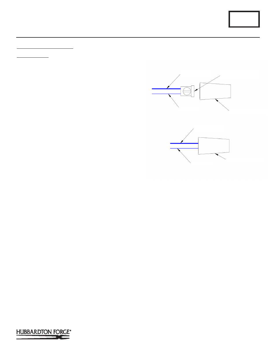
To Install Wire Connectors
(Figure 4)
Component Parts
H Support Cable (2)
O Black Isolation Sleeve (2)
T Red Wire (2)
U Set Screw Sleeve
V Insulating Shell
1. Insert support cable (H) and red wire (T) into set screw
sleeve. Wire insulation and black isolation sleeve (O) must
rest against threaded shoulder.
2. Tighten set screw.
3. Trim excess support cable (H) and red wire (T) flush with
end of set screw sleeve (U).
4. Screw insulating shell (V) onto set screw sleeve (U) until
tight.
A362
For Aperture Pendant 137901
Page 4 of 4
(Figure 4)
(Continued)
SUPPORT CABLE
SET SCREW SLEEVE
INSULATING SLEEVE
RED WIRE
RED WIRE
SUPPORT CABLE
INSULATING SLEEVE