A362, Assembly & installation instructions – Hubbardton Forge 137901 User Manual
Page 2
If you need further assistance, or find that you are missing any parts, please contact the dealer from which you purchased this product.
We hope you enjoy your fixture!
* Hubbardton Forge will not be liable for injury or damage caused by improper installation, lamping or use of this fixture.
H U B B A R D T O N F O R G E . C O M
hand-forged, vermont-made lighting and accessories
154 RT. 30 SOUTH
•
CASTLETON, VERMONT 05735
All designs and images ©1989-2014 Hubbardton Forge
®
. All rights reserved.
30715 Rev B
Assembly & Installation Instructions
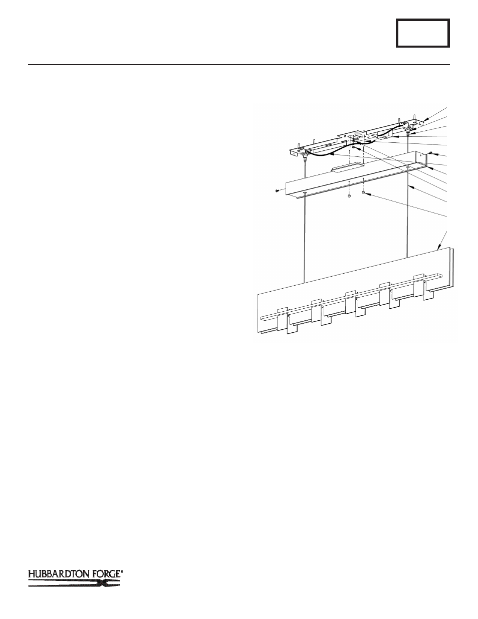
6. Install threaded studs (D) into mounting bracket (B).
7. Slide support cables (H) through larger holes in canopy (I) as
show in Figure 2. Rest canopy (I) on top of fixture (L).
8. Loosen cable gripper locks (N) before trying to install cables.
Note: Support cables (H) will not be able to pass through the cable
gripper (G) unless the locks are loose.
9. Raise fixture and push support cables (H) into the cable
grippers (G) until desired fixture height is accomplished and
level. Once desired height is accomplished and product is
level, tighten cable gripper locks (N). (Figure 2).
10. Slip a black isolation sleeve (O) (provided) over the end of
the each support cable (H) and trim cables leaving
½” of length past end of sleeve to make connections.
Important: Cables need to be completely covered from gripper to
wire connector. If any portion of the cable comes in contact with
metal the fixture wires will short and fixture will stop working.
11. Using suitable wire connectors (provided) connect support
cable (H) to one red wire on the transformer (M). Connect
the remaining support cable (H) to the red wire remaining
from the transformer (M).
CAUTION: MAKE SURE WIRE CONNECTORS ARE TWISTED ON
SECURELY, AND NO BARE WIRE IS EXPOSED.
12. Using suitable wire connectors (not provided) connect fix
ture wires to supply (white to white and black to
black). Raise canopy (I) up close to mounting bracket (B).
Using cupped washer (E) and green ground screw (F) (pro-
vided in mounting kit), run a pigtail from mounting bracket
(B) to junction box. Connect all ground wires (bare copper
or green to bare copper or green). Push wires back into
junction box.
CAUTION: MAKE SURE WIRE CONNECTORS ARE TWISTED ON
SECURELY, AND NO BARE WIRE IS EXPOSED.
13. Push canopy (I) over threaded studs (D) and firmly to ceiling,
making sure that no wires are pinched between canopy and
ceiling. Secure the canopy by attaching knurled balls (K)
to the threaded studs (D), then threading #8 screws (J)
through the ends of the canopy (I) into the threaded holes in
the bracket (B).
14. Continue with bulb and glass installation next.
A362
For Aperture Pendant 137901
Page 2 of 4
(Figure 2)
(Continued)
B
G
N
M
D
J
I
(Continued)
E
F
H
K
L