Component parts, A313, Assembly & installation instructions – Hubbardton Forge 137725 User Manual
Page 2
Assembly & Installation Instructions
A313
Erlenmeyer Pendant 137725
Page 2 of 4
Hand-Forged, Vermont-Made Lighting and Accessories
154 Route 30 South, Castleton, Vermont 05735
27331
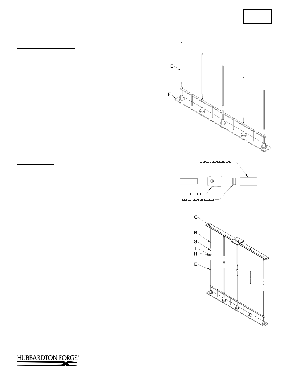
To Attach Fixture Pipes
(Figure 2)
Component Parts
E Fixture Pipe (5)
F Fixture
1. Carefully thread fixture pipe (E), threaded end first, over
fixture wires.
2. Apply a drop of supplied thread locking compound to the
internal threads at the top of the fixture (F) and screw stem
into fixture, being careful not to twist wires.
Note: Application of the thread locking compound is
necessary to prevent the stem from loosening during regular
maintenance and cleaning of the fixture. Be sure to apply
the compound.
To Complete Fixture Assembly
(Figures 3 & 4)
Component Parts
B Canopy Pipe (5)
E Fixture Pipe (5)
G Plastic Clutch Sleeve (5)
H Clutch (5)
I
Set Screw (5)
1. Thread the wires from the fixture pipe (E) into and through the
canopy pipe (B) up through the hex nipple (C).
2. Unscrew the clutch (H) from the canopy pipe (B); slide it across the
wires and onto the fixture pipe (E). Follow this with the plastic
clutch sleeve (H), oriented so the tapered end of the clutch sleeve
nests in the clutch (Figure 3).
3. Slide the canopy pipe (B) as far as necessary to give you the total
length of the fixture which you desire. Be careful not to scratch the
pipe surfaces and to pull excess wire up through the canopy pipe (B).
Screw clutch (H) onto canopy pipe (B). There must be a minimum
1-1/2" of inner pipe inside the outer pipe. Hand-tighten the clutch to
temporarily hold this adjustment. The clutch is not securely fastened
at this point; do not depend on it to hold the fixture.
Important: To ensure full connection strength, be sure the tapered
end of the plastic clutch sleeve is oriented toward the clutch when
assembled and securely tighten set screw
(Figure 4).
4. Continue with ceiling installation below.
(continued)
(Figure 3)
(Figure 2)
(Figure 4)