A120, Assembly & installation instructions – Hubbardton Forge 137545 User Manual
Page 2
Assembly & Installation Instructions
A120
For Exos Wave Five-Light Pendant 13-7545
Page 2 of 3
Hand-Forged,
Vermont-Made Lighting and Accessories
P.O. Box 827, 154 Route 30 South, Castleton, Vermont 05735
19890 Rev A
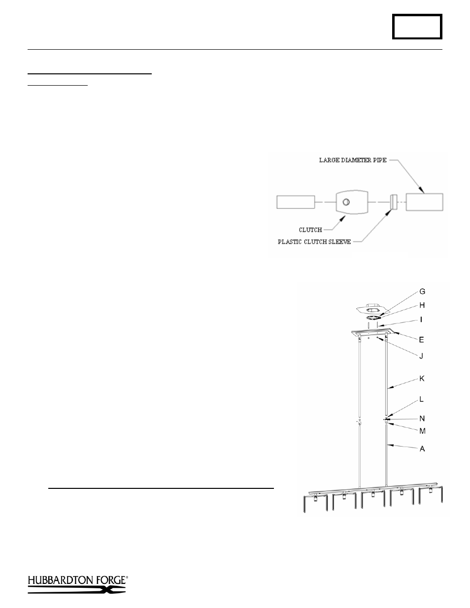
To Complete Fixture Assembly
(Figures 3 & 4)
Component Parts
A Fixture Pipe (2)
I
Threaded Stud (2)
M Clutch
(2)
E Canopy
J Knurl Ball (2)
N Set Screw (2)
G Crossbar
K Canopy Pipe (2)
H Ground
Screw
L Plastic Clutch Sleeve (2)
Caution: Be sure power is off at the main breaker box prior to installation.
1. Thread the wires from the fixture pipe (A) into and
through the canopy pipe (K) up through the canopy (E).
2. Unscrew the clutch (M) from the canopy pipe (K); slide it
across the wires and onto the fixture pipe (A). Follow this
with the plastic clutch sleeve (L), oriented so the tapered
end of the clutch sleeve nests in the clutch.
3. Slide the canopy pipe (K) as far as necessary to give you
the total length of the fixture which you desire. Be careful
not to scratch the pipe surfaces and to pull excess wire up
through the canopy pipe (K). Screw clutch (M) onto
canopy pipe (K). There must be a minimum 1-1/2" of
inner pipe inside the outer pipe. Hand-tighten the clutch to
temporarily hold this adjustment. The clutch is not securely
fastened at this point; do not depend on it to hold the fixture.
Important: To ensure full connection strength, be sure the tapered end
of the plastic clutch sleeve is oriented toward the clutch when
assembled and securely tighten set screw (Figure 3).
4. Thread studs (I) through appropriate holes in crossbar (G) to match
holes in canopy (E).
5. Using two machine screws (not provided), fasten the crossbar (G) to
the electric box.
Note: A new electric box comes with screws. When replacing a fixture,
retain the existing screws for use with the new fixture.
6. Using suitable wire connectors (not provided) connect fixture wires to
supply (white to white and black to black). Connect all ground wires to
green ground screw (H).
Caution: Make sure wire connectors are twisted on securely, and no bare
wire is exposed.
7. Slide canopy (E) over threaded studs (I) and push firmly to ceiling,
making sure that no wires are pinched between
fixture canopy and ceiling. Fasten with knurled balls (J).
Be sure studs are fully seated in the knurled balls.
Note: Be sure both swivel notches are aligned in the same direction.
For sloped ceilings the notches should face towards the down side.
8. Once the fixture is fastened to the ceiling, tighten the set screw (N)
firmly with hex wrench provided. Only after the set screw (N) is tight
should you install the glass.
(Figure 4)
(Figure 3)
9. Refer instructions below and install glass.
10. Restore electricity at main breaker.
(continued)