A179, Assembly & installation instructions – Hubbardton Forge 137530F User Manual
Page 3
Assembly & Installation Instructions
A179
For Ellipse Circular Adjustable Pendant 13-7530F
Page 3 of 4
Hand-Forged,
Vermont-Made Lighting and Accessories
P.O. Box 827, 154 Route 30 South, Castleton, Vermont 05735
21365
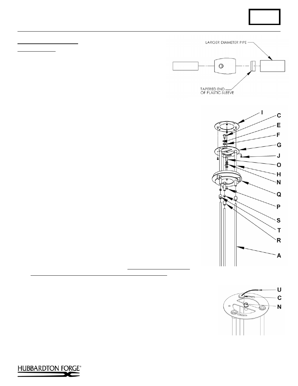
Install Fixture to Ceiling
(Figures 4, 5 & 6)
Component Parts
A Fixture Pipe (3)
C Cable
Gripper
E Flat
Washer
F Lock
Washer
G Support
Ring
H Canopy
Pipe
I Crossbar
J 10-32
Screw
(4)
N Ground
Wire
O Threaded
Nipple
P Threaded
Button
Q Canopy
R Clutch
(3)
S Plastic Clutch Sleeve (3)
T Set Screw (2)
U Cable
Caution: Be sure power is off at the main breaker box prior to installation.
1. Place canopy (Q) over canopy pipes (H).
2. Reinstall clutch sleeve (S) and clutch (R) onto canopy pipes (H).
3. Remove cable gripper (C) from support ring along with flat washer (E) and
lock washer (F).
4. Thread wires and support cable (U) from the fixture pipe (A) through the
canopy pipe (H) and out of top side of support ring (G). Make sure the cable
(U) is aligned with the hole the cable gripper (C) will be installed in.
Note: Cable and wires are in separate pipes.
5. Pull the cable (U) through the lock washer (F), flat washer (E) and cable
gripper (C).
6. Apply a drop of the supplied thread locking compound to the external
threads of the cable gripper (C). Slip flat washer (E) and lock washer (F)
over cable gripper (C). Slip cable gripper (C) through support ring (G) and
thread into canopy pipe (H).
7. Unscrew the clutch (R) from the canopy pipe (H); slide it across the wires
and onto the fixture pipe (A). Follow this with the plastic clutch sleeve (S),
oriented so the tapered end of the clutch sleeve nests in the clutch (Figure 4).
8. Slide the canopy pipes (H) as far as necessary to give you the total length of
the fixture which you desire. Be careful not to scratch the pipe surfaces and
to pull excess wire up through the canopy pipes (H). There must be a
minimum 1-1/2" of inner pipe inside the outer pipe. Hand-tighten the
clutches to temporarily hold this adjustment. The clutches are not securely
fastened at this point; do not depend on them to hold the fixture.
Important: To ensure full connection strength, be sure the tapered end of
the plastic clutch sleeve is oriented toward the clutch when assembled and
securely tighten set screw (Figure 4).
9. Pull cable (U) through cable gripper (C) until tight. Remove excess cable
(Figure 6)
.
10. Raise fixture to ceiling aligning two 10-32 screws (J) installed in the cross
bar previously with the keyed slots in the support ring (G). Turn fixture until
all four holes in the support ring (G) align with the threads in crossbar (I).
Tighten the screws.
11. Install the other two 10-32 screws (J).
(continued)
(Figure 6)
(Figure 4)
(Figure 5)