A179, Assembly & installation instructions – Hubbardton Forge 137530F User Manual
Page 2
Assembly & Installation Instructions
A179
For Ellipse Circular Adjustable Pendant 13-7530F
Page 2 of 4
Hand-Forged,
Vermont-Made Lighting and Accessories
P.O. Box 827, 154 Route 30 South, Castleton, Vermont 05735
21365
Prepare the Canopy
(Figure 3)
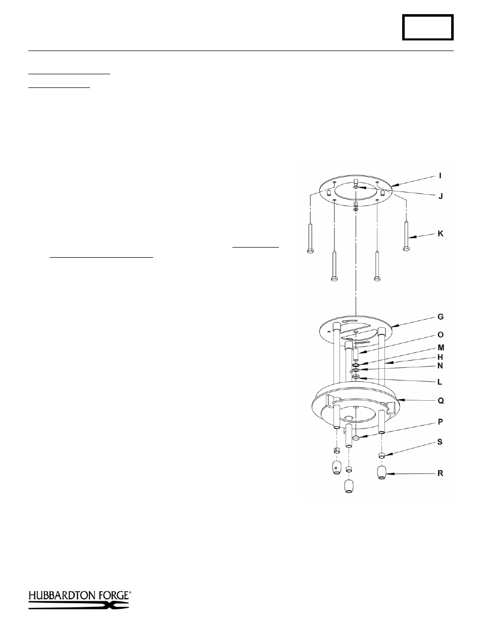
Component Parts
C Cable
Gripper
G Support
Ring
H Canopy
Pipe
I Crossbar
J 10-32
Screw
(4)
K Lag Screw (4)
L Jam
Nut
M Lock
Washer
N Ground
Wire
O Threaded
Nipple
P Threaded
Button
Q Canopy
R Clutch
S Clutch
Sleeve
Caution: Be sure power is off at the main breaker box prior to
installation.
1. Using four lag screws (K) attach crossbar (I) to a structural
member in the ceiling, centering the crossbar over the outlet box.
We've supplied lag screws with your fixture; however, different
materials and/or construction methods may require different
fasteners. If in doubt, contact a qualified electrician. Do not attach
crossbar directly to outlet box.
2. Thread jam nut (L), ground wire (N) and lock washer (M) onto
threaded nipple (O); leave parts loose. Thread into center hole of
support ring (G).
3. Install two 10-32 screws (J) into crossbar (I). Thread in only a
couple of threads.
4. Remove three clutches (R) and plastic clutch sleeves (S). Set
aside for later use.
5. Raise support ring (G) with three canopy pipes (H) installed up to
crossbar (I) aligning keyed slots with the two screws installed in
the crossbar.
6. Turn support ring (G) until it stops.
7. Temporally tighten two 10-32 screws (J).
8. Slip canopy (Q) up the three canopy pipes (H) until it rests
against the ceiling.
9. Adjust threaded nipple (O) in the center of the crossbar (I) until it
protrudes approximately 1/8" below the canopy (Q).
10. When the correct adjustment is established, tighten jam nut (L)
against crossbar (I) to hold the adjustment.
11. Remove the canopy (Q) and support ring (G) from the crossbar
(I) by loosening the two 10-32 screws (J).
(continued)
(Figure 3)