A324, Assembly & installation instructions – Hubbardton Forge 136510 User Manual
Page 2
Assembly & Installation Instructions
A324
Corona Triple Pendant 13-6510
Page 2 of 3
Hand-Forged, Vermont-Made Lighting and Accessories
154 Route 30 South, Castleton, Vermont 05735
28099 Rev A
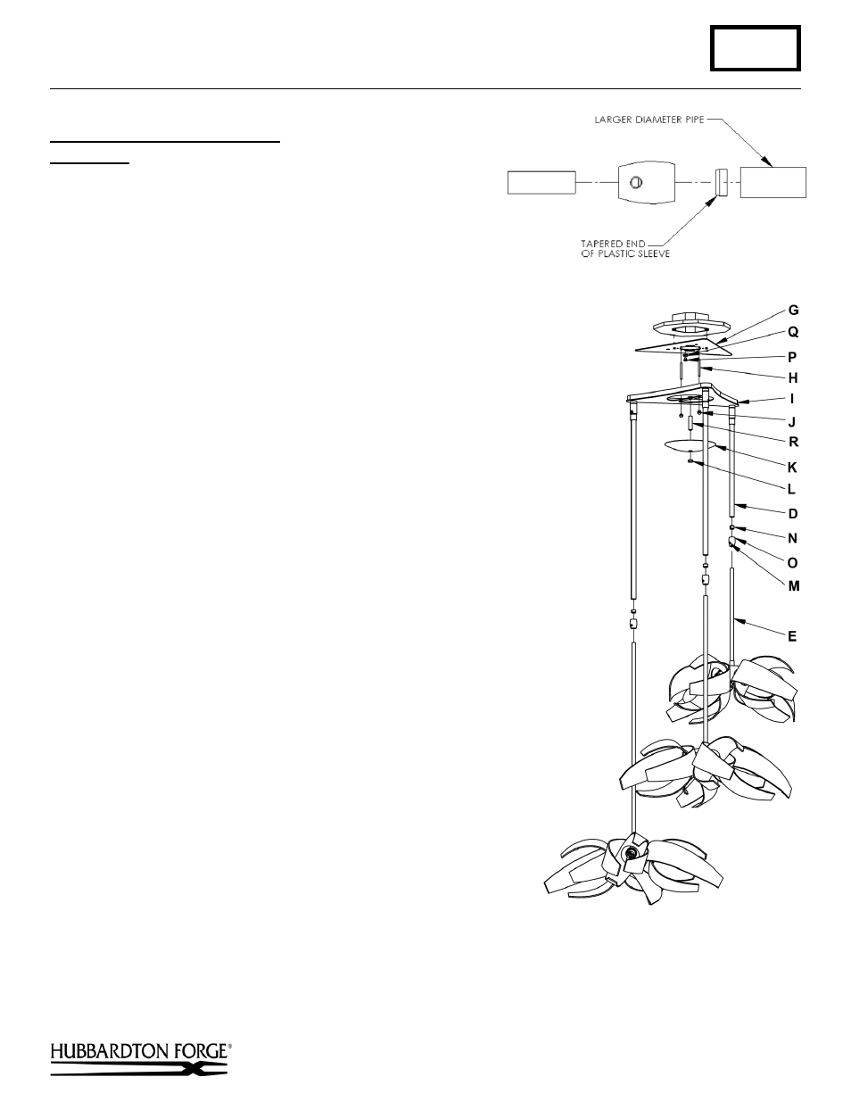
To Assemble and Install Fixture
(Figures 3 & 4)
Components
D
Canopy Pipe (3)
E
Fixture Pipe (3)
G
Crossbar
H
Threaded Studs (2)
I
Canopy
J
Knurl Ball (2)
K
Canopy Cover
L
Lock Up
M
Set Screw (3)
N
Clutch Sleeve (3)
O
Clutch (3)
P
Ground Screw
Q
Cupped Washer
R
Canopy Nipple
1. Carefully unpack fixture from carton.
2. Thread the wires from the fixture pipe (E) into and through the
canopy pipe (D) up through the canopy (I).
3. Unscrew clutch (O) from canopy pipe (D), slide it across the wires
and onto the fixture pipe (E). Follow this with the clutch sleeve
(N), so it nests in clutch (O).
4. Slide the fixture pipe (E) up into canopy pipe (D) as far necessary
to give you the total length of the fixture which you desire. Be
careful not to scratch the pipe surfaces and to pull excess wire up
through the canopy (I). There must be a minimum 1-1/2" of
inner pipe inside the outer pipe. Hand-tighten the clutch to
temporarily hold this adjustment. At this point the adjustment is
not securely fastened; do not depend on it to hold the fixture.
Important: To ensure full connection strength, be sure the
tapered end of the plastic clutch sleeve is oriented toward the
clutch when assembled and securely tighten set screw (Figure 3).
5. Thread studs (H) through appropriate holes in the crossbar (G) to
match hole centers in canopy (I).
6. Using two machine screws (not provided), fasten the crossbar (G)
to the electric box using outer oval slots to orient fixture to desired
hanging position.
Note: A new electric box comes with screws. When replacing a
fixture, retain the existing screws for use with the new fixture.
7. Slide fixture canopy (I) with fixture attached, over threaded studs
(H) and push firmly to ceiling making sure no wires are pinched
between fixture canopy and ceiling. Fasten with knurled balls (J).
Be sure studs (H) are fully seated in knurled balls (J).
8. Using suitable wire connectors (not provided) connect fixture
wires to supply (white to white and black to black). Run a pigtail
lead from crossbar ground screw (P) and cupped washer (Q) to the
junction box and connect all ground wires (bare copper or green to
bare copper or green).
Caution: Make sure wire connectors are twisted on securely, and
no bare wire is exposed.
9. Check fixtures for height and level.
10. Once the fixture is fastened to the ceiling, tighten the set screws (M) on the clutches firmly with hex wrench
provided. Only after the set screws (M) are tight should you install the glass.
11. Repeat for all three fixtures
(continued)
(Figure 3)
(Figure 4)