A202, Assembly & installation instructions – Hubbardton Forge 136303 User Manual
Page 3
Assembly & Installation Instructions
A202
For Pendant 13-6303 & 13-6303E
Page 3 of 3
Hand-Forged,
Vermont-Made Lighting and Accessories
P.O. Box 827, 154 Route 30 South, Castleton, Vermont 05735
22699 Rev A
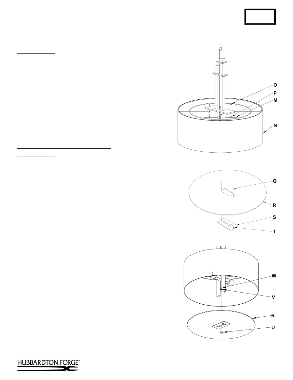
Install Shade
(Figure 5)
Component Parts
M Spider
N Shade
O Knurl
Balls
(4)
P Threaded Studs (4)
1. Slip shade (N) from bottom of fixture so it goes past
spider (M).
2. Aligning the four holes in the shade (N) with the threaded
studs (P) lower the shade onto the spider.
3. Thread the four knurl balls (O) onto the threaded studs (P)
and tighten until snug.
Assemble and Install Bottom Diffuser
(Figures 6 & 7)
Component Parts
Q Threaded Ball (2)
R Diffuser
S Bottom
Plate
T Threaded Studs (2)
U Threaded
Cap
V Pipe
W Stop
1. Align threaded studs (T) in bottom plate (S) with holes in diffuser
(R) so the studs pass through the diffuser (Figure 6).
2. Install threaded balls (Q) onto threaded studs (T) and tighten until
snug. Do not over tighten (Figure 6).
3. Install light bulbs. (Fluorescent fixtures; bulbs are included.)
4. Remove threaded cap (U) from pipe (V). Save for later use. Cap
is shipped installed on fixture.
5. Slip diffuser (R) onto pipe (V) aligning slots in the bottom plate
(S) with the forged bars in the fixture until diffuser rests against
stop (W). Install threaded cap (U) until snug against bottom
plate (S). Note: It may be necessary to straighten pipe (V) by
hand to allow diffuser to sit straight. Pipe is sometimes bent to
one side due to shipping.
6. Restore electricity at main breaker.
If you need further assistance, or find that you are missing any parts,
please contact the dealer from which you purchased this product. We
hope you enjoy your fixture!
* Hubbardton Forge will not be liable for injury or damage caused by
improper installation, lamping or use of this fixture.
(Figure 5)
(Figure 7)
(Figure 6)