A251, Assembly & installation instructions – Hubbardton Forge 134501 User Manual
Page 2
If you need further assistance, or find that you are missing any parts, please contact the dealer from which you purchased this product.
We hope you enjoy your fixture!
* Hubbardton Forge will not be liable for injury or damage caused by improper installation, lamping or use of this fixture.
H U B B A R D T O N F O R G E . C O M
hand-forged, vermont-made lighting and accessories
154 RT. 30 SOUTH
•
CASTLETON, VERMONT 05735
All designs and images ©1989-2013 Hubbardton Forge
®
. All rights reserved.
24621 Rev A
Assembly & Installation Instructions
Complete Assembly & Install Fixture
(Figures 2 & 3)
(Continued)
1. Carefully thread fixture pipe (G), threaded end first, over
fixture wires.
2. Apply a drop of the supplied thread locking compound to
the internal threads of fixture coupling and screw stem into
fixture, being careful not to twist or pinch the wires.
Note: A new electric box comes with screws. When replacing a
fixture, retain the existing screws for use with the new fixture.
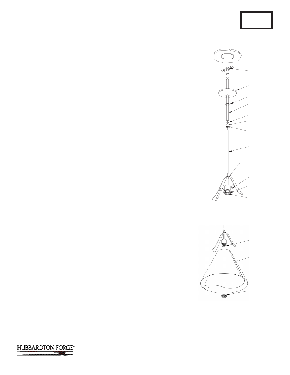
3. Place canopy (D) over canopy pipe (F), followed by canopy
ring (E). Make sure smaller diameter side of canopy ring is
oriented up toward the canopy.
4. Thread wires from the fixture pipe (G) through the canopy
pipe (F).
5. Unscrew the clutch (I) from the canopy pipe (F); slide it
across the wires and onto the fixture pipe (G). Follow this
with the plastic clutch sleeve (H), oriented so the tapered
end of the clutch sleeve nests in the clutch. (Figure 2).
6. Slide the canopy pipe (F) as far as necessary to give you
the total length of the fixture which you desire. Be care
ful not to scratch the pipe surfaces and to pull excess wire
up through the canopy pipe (F). There must be a minimum
1-1/2" of inner pipe inside the outer pipe. Hand-tighten the
clutch to temporarily hold this adjustment. The clutch is
not securely fastened at this point; do not depend on it
to hold the fixture. Important: To ensure full connection
strength, be sure the tapered end of the plastic clutch
sleeve is oriented toward the clutch when assembled and
securely tighten set screw (Figure 3).
7. Carefully slide canopy ring (E) and canopy (D) down
over fixture pipe (G) until they rest on the fixture.
8. Using two machine screws (not provided), fasten the
crossbar to the electric box.
Note: A new electric box comes with screws. When replacing a
fixture, retain the existing screws for use with the new fixture.
A251
Adjustable Mobius Shade Pendant 134501
Page 2 of 6
D
E
F
H
(Figure 4)
K
(Figure 3)
I
J
G
L
M
N
FIXTURE
COUPLING
N
O
M