Hubbardton Forge 134501 User Manual
A251, Assembly & installation instructions
H U B B A R D T O N F O R G E . C O M
hand-forged, vermont-made lighting and accessories
154 RT. 30 SOUTH
•
CASTLETON, VERMONT 05735
All designs and images ©1989-2013 Hubbardton Forge
®
. All rights reserved.
24621 Rev A
Assembly & Installation Instructions
If you need further assistance, or find that you are missing any parts, please contact the dealer from which you purchased this product.
We hope you enjoy your fixture!
* Hubbardton Forge will not be liable for injury or damage caused by improper installation, lamping or use of this fixture.
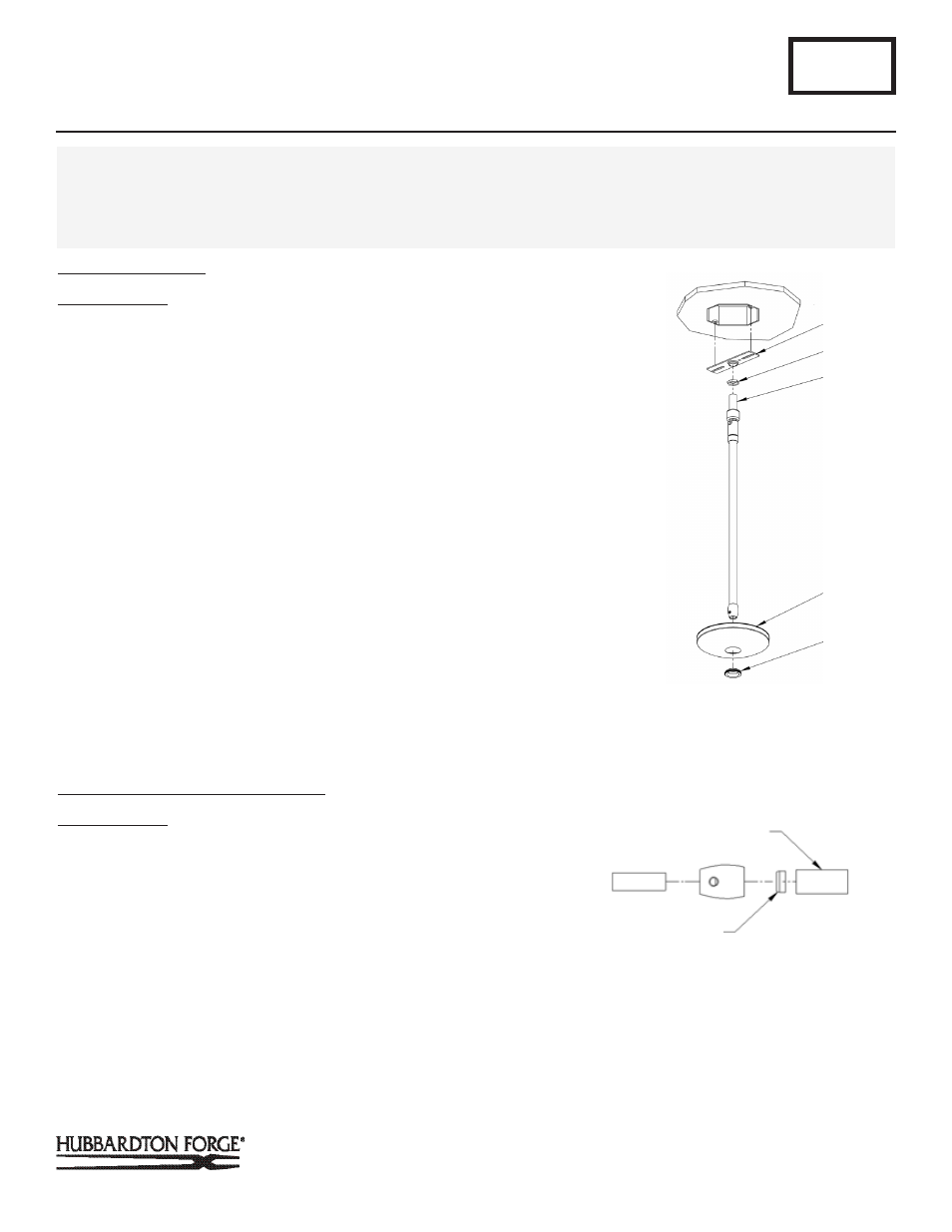
Prepare the Canopy
(Figure 1)
Component Parts
A Jam Nut
B Crossbar
C Threaded Nipple
D Canopy
E Canopy Ring
CAUTION: BE SURE POWER IS OFF AT THE MAIN BREAKER BOX
PRIOR TO INSTALLATION.
1. Thread jam nut (A) and crossbar (B) onto threaded nipple
(C); leave both parts loose.
2. Using two machine screws (not provided), temporarily fasten
the crossbar (B) to the electric box.
Note: A new electric box comes with screws. When replacing a
fixture, retain the existing screws for use with the new fixture.
3. Adjust the length of threaded nipple (C) in crossbar (B) so
that canopy ring (E) will hold canopy (D) against the ceiling
with no threads showing for best appearance. When the
correct adjustment is established, tighten jam nut (A) against
crossbar (B) to hold the adjustment.
4. Remove the crossbar and stem from the electrical box and
proceed with the assembly instructions.
Complete Assembly & Install Fixture
(Figures 2 & 3)
Component Parts
C Canopy
E Canopy Ring
F Canopy Pipe
G Fixture Pipe
H Plastic Sleeve
I Clutch
CAUTION: BE SURE POWER IS OFF AT THE MAIN BREAKER BOX
PRIOR TO INSTALLATION.
A251
Adjustable Mobius Shade Pendant 134501
Page 1 of 6
CAUTION: FAILURE TO INSTALL THIS FIXTURE PROPERLY MAY RESULT IN SERIOUS PERSONAL INJURY OR DEATH AND
PROPERTY DAMAGE. We recommend installation by a licensed electrician. This product must be installed in accordance with
applicable installation code(s), by a person familiar with the construction and operation of the product and the hazards involved.*
Caution: Do not exceed maximum wattage noted on fixture. Use only recommended bulbs with fixture.
(Figure 2)
A
(Figure 1)
C
B
D
J Set Screw
K Ground Screw
L Shade Spider
M Retaining Ring
N Socket
E
(Figure 1)
LARGER DIAMETER PIPE
TAPERED END OF
PLASTIC SLEEVE