Tableb2: rj45 pin assignments, Tableb3: ata10 and ata11 specifications – Allied Telesis AT-FS724 User Manual
Page 62
7HFKQLFDO#6SHFLILFDWLRQV
B-2
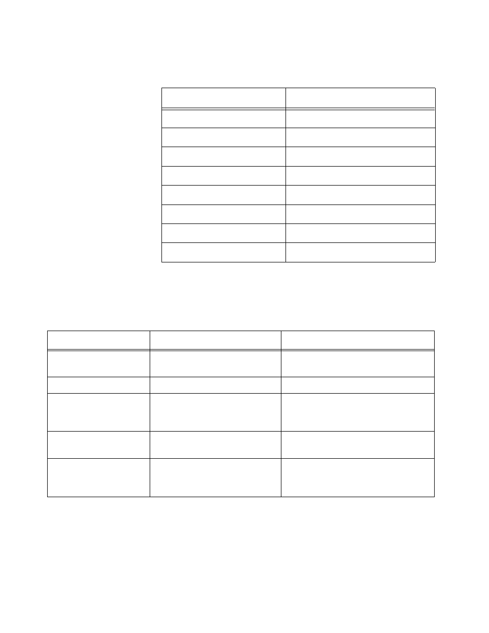
Table B-2 shows the pin assignments for the switches’ RJ45
connectors.
Table B-3 lists the specifications for the AT-A10 and AT-A11 media
dependent adapters. The MDAs are installed in the AT-FS718 switch’s
uplink slots.
Table B-2: RJ45 Pin Assignments
Pin
Number Function
1
RD+
2
RD-
3
TD+
4
Unused
5
Unused
6
TD-
7
Unused
8
Unused
Table B-3: AT-A10 and AT-A11 Specifications
AT-A10
AT-A11
Physical Dimensions
(H x W x D)
0.85 in x 3 in x 4.5 in
(2.16 cm x 7.62 cm x 11.43 cm)
0.85 in x 3 in x 4.5 in
(2.16 cm x 7.62 cm x 11.43 cm)
Weight
.10 lbs (.045 kg)
.10 lbs (.045 kg)
Connector Type
RJ45
SC multimode fiber
50/125- and 62.5/125-micron
multimode fiber cable
Maximum Distance
328 ft (100 m)
Category 5 UTP
Half-duplex: 1,351 ft (412 m)
Full-duplex: 1.25 miles (2 km)
Ethernet Mode
10Base-T/100Base-TX
Auto-negotiating
Half- or Full-duplex
100Base-FX
Half- or Full-duplex