Figure11 the atfs724 switch (front), Figure12 the atfs718 switch (front), Figure13 the switch rear panel – Allied Telesis AT-FS724 User Manual
Page 12: Dugzduh#'hvfulswlrq, Uplink slots (port a and port b)
+DUGZDUH#'HVFULSWLRQ
1-2
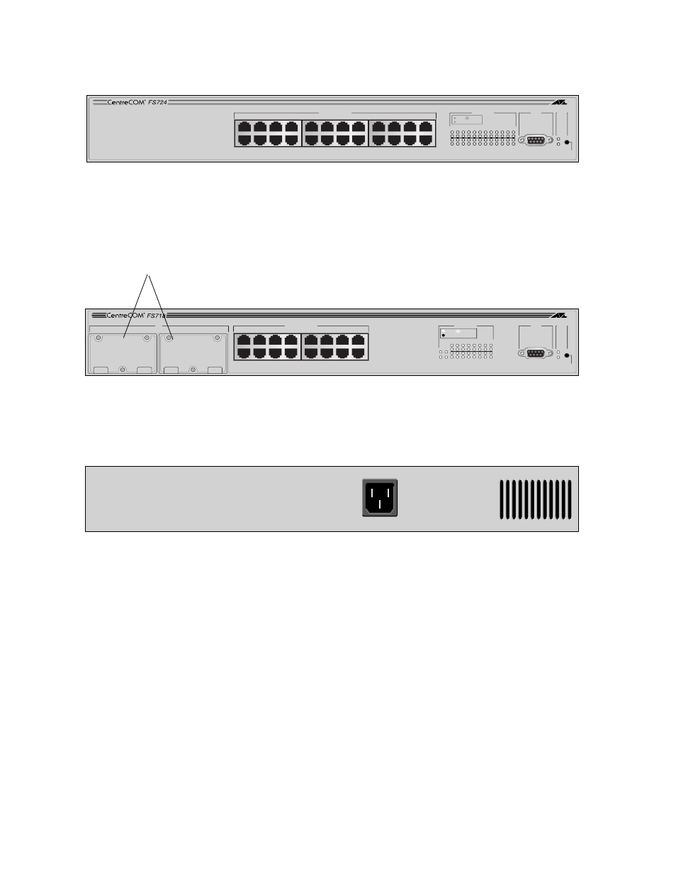
Figure 1-1 shows the 24-port model that has no uplink option slots.
Figure 1-1 The AT-FS724 Switch (Front)
Figure 1-2 shows the 16-port model with slots for uplink options.
Figure 1-2 The AT-FS718 Switch (Front)
Figure 1-3 shows the rear panel of the switch.
Figure 1-3 The Switch Rear Panel
RS-232
TERMINAL PORT
STATUS
RESET
FAULT
POWER
10BASE-T / 100BASE-TX
FAST ETHERNET SWITCH
PORT ACTIVITY
1
3
5
7
9
11
13
15
17
19
21
23
2
4
6
8
10
12
14
16
18
20
22
24
LINK / RECEIVE
100M
10BASE-T / 100BASE-TX
1X
3X
5X
7X
2X
4X
6X
8X
9X
11X
13X
15X
17X
19X
21X
23X
10X
12X
14X
16X
18X
20X
22X
24X
MDA
A
B
RS-232
TERMINAL PORT
STATUS
RESET
FAULT
POWER
10BASE-T / 100BASE-TX
FAST ETHERNET SWITCH
PORT ACTIVITY
1
3
5
7
9
11
13
15
2
B
A
4
6
8
10
12
14
16
10BASE-T / 100BASE-TX
1X
3X
5X
7X
2X
4X
6X
8X
9X
11X
13X
15X
10X
12X
14X
16X
LINK /
RECEIVE
100M
Uplink slots (Port A and Port B)
POWER