Installing the switch in the rack, Figure21 removing the feet, Figure22 attaching rackmounting brackets – Allied Telesis AT-FS724 User Manual
Page 25: Qvwdoolqj#wkh#6zlwfk#lq#wkh#5dfn
$70)6:4;#DQG#$70)6:57#,QVWDOODWLRQ#*XLGH
2-5
,QVWDOOLQJ#WKH#6ZLWFK#LQ#WKH#5DFN
Caution
Do not use power tools to perform this installation.
1. Remove all cables and power cord from the switch (if previously
attached).
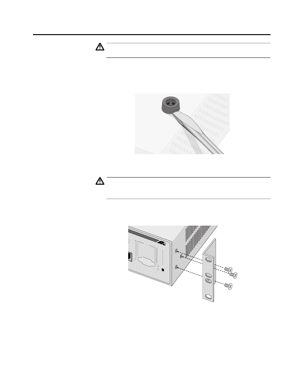
2. Remove the snap-on plastic feet, as shown in Figure 2-1.
Figure 2-1 Removing the Feet
Caution
Air vents must not be blocked and must have free access to the room
ambient air for cooling.
'
13
3. Attach the rackmounting brackets to each side of the switch,
using the 6 flathead screws that came with the switch package.
Figure 2-2 Attaching Rackmounting Brackets
4. Mount the switch in the rack using standard screws (not
provided).
Ensure that there is unrestricted air flow around the switch.
OR POR
T
RS-232
TERMINAL POR
T
STATUS
RESET
K
FAUL
T
POWER