Physical description, 3k\vlfdo#'hvfulswlrq, Reset button – Allied Telesis AT-FS724 User Manual
Page 15: System and port status leds
$70)6:4;#DQG#$70)6:57#,QVWDOODWLRQ#*XLGH
1-5
3K\VLFDO#'HVFULSWLRQ
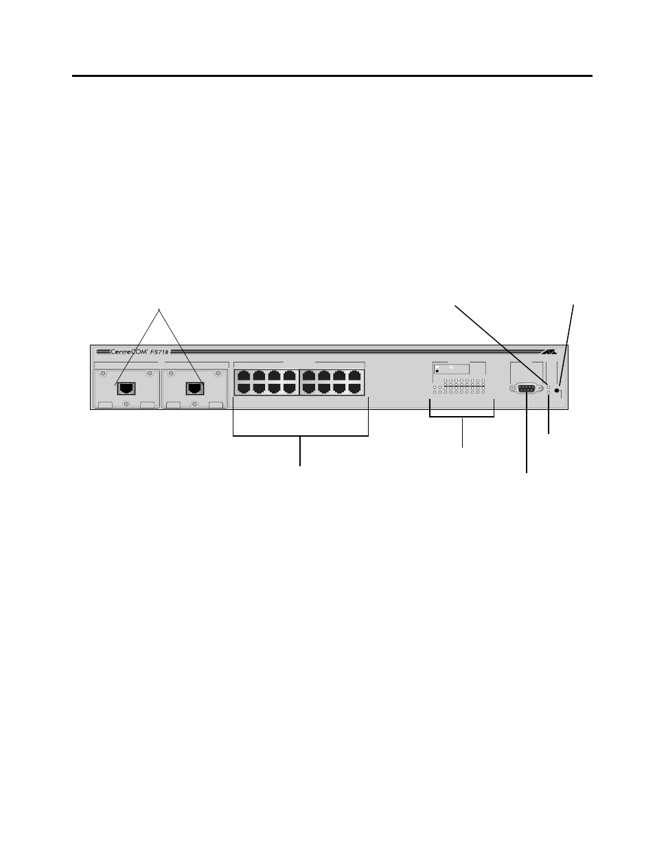
The switches have the following major front panel components:
❑
16 or 24 Ethernet 10Base-T/100Base-TX unshielded twisted
pair (RJ45) ports
❑
RS232 (DB9-F) connector for port configuration, and
diagnostics or software update
❑
Reset button
❑
System and port status LEDs
❑
Two slots, Port A and Port B, for optional 100Base-TX or
100Base-FX backbone connectivity on the AT-FS718.
Figure 1-4 The AT-FS718 Switch With Fully-Populated Uplink Slots
MDA
A
B
RS-232
TERMINAL PORT
STATUS
RESET
FAULT
POWER
10BASE-T / 100BASE-TX
FAST ETHERNET SWITCH
PORT ACTIVITY
1
3
5
7
9
11
13
15
2
B
A
4
6
8
10
12
14
16
10BASE-T / 100BASE-TX
1X
3X
5X
7X
2X
4X
6X
8X
9X
11X
13X
15X
10X
12X
14X
16X
AT-A10
100BASE-TX
X
AT-A10
100BASE-TX
X
LINK /
RECEIVE
100M
Auto-negotiating 10Base-T/100Base-TX Ports
Port LEDs
RS232 connector
Fault LED
Reset button
Media dependent adapters (optional)
Power LED