Switch leds, Table31 switch leds, 6zlwfk#/('v – Allied Telesis AT-FS724 User Manual
Page 43
$70;)6:4;#DQG#$70)6:57#,QVWDOODWLRQ#*XLGH
3-3
6ZLWFK#/('V
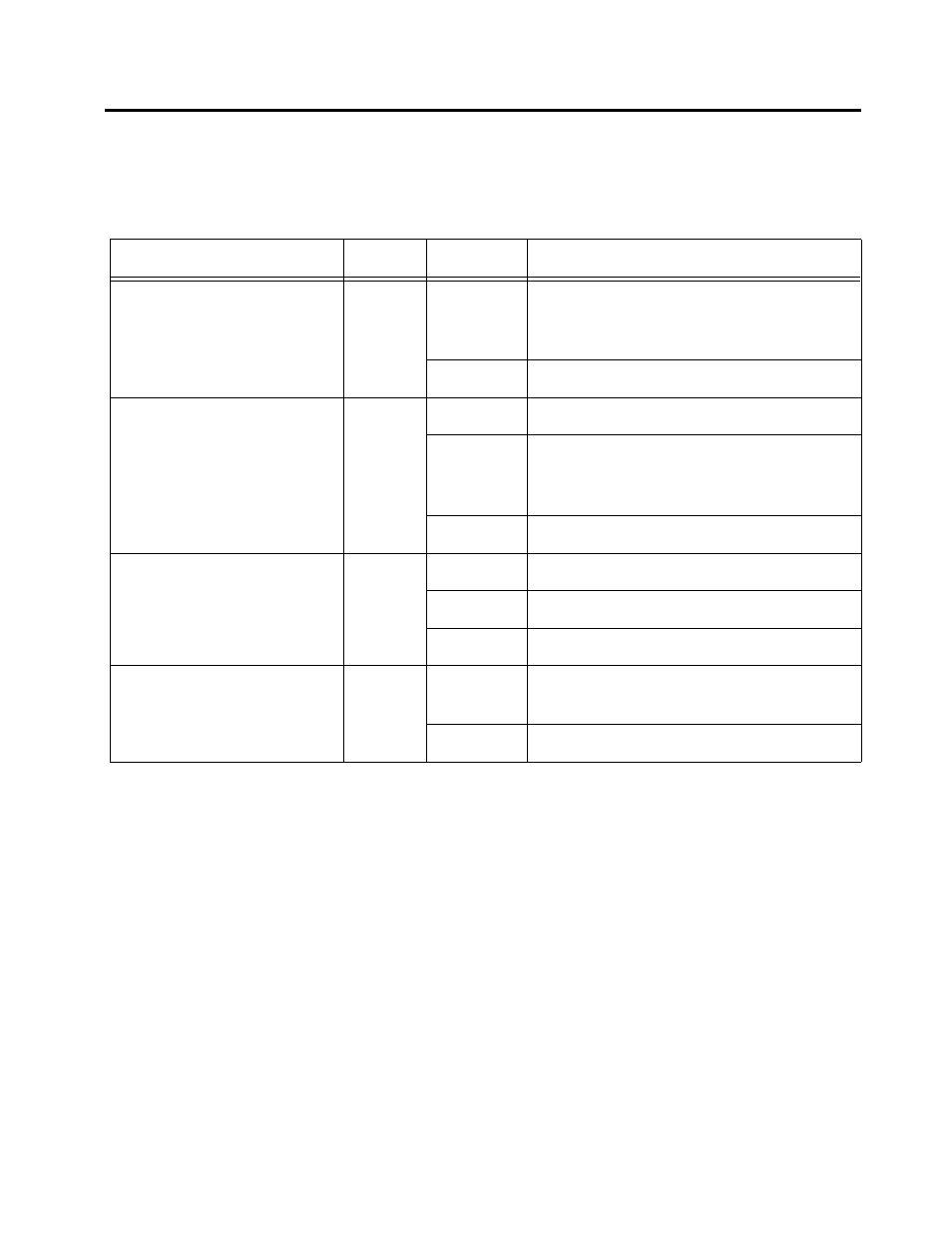
The switch LEDs indicate proper operation or problems with the port
and power. Table 3-1 describes the switch LEDs.
Table 3-1 Switch LEDs
LED
Color
State
Description
POWER (system)
Green
On
The switch is receiving power, voltage is
within the acceptable range, and the
power supply is working.
Off
No power.
FAULT (system)
Red
On
The switch is malfunctioning.
Flashing
The switch is booting, running
diagnostics, writing images to FLASH, or
transferring files via XMODEM.
Off
Normal operation.
Link/Receive
(port, top row)
Green
On
There is a physical link with a device.
Flashing
The port is receiving packets.
Off
No link.
100M
(port, bottom row)
Amber
On
The port is operating at 100 Mbps, or is
manually configured to 100Base-TX.
Off
The port is operating at 10 Mbps.