The switch in workgroup configurations, Figure42 switches in workgroup configurations, 7kh#6zlwfk#lq#:runjurxs#&rqiljxudwlrqv – Allied Telesis AT-FS724 User Manual
Page 48
6ZLWFK#&RQILJXUDWLRQV
4-2
7KH#6ZLWFK#LQ#:RUNJURXS#&RQILJXUDWLRQV
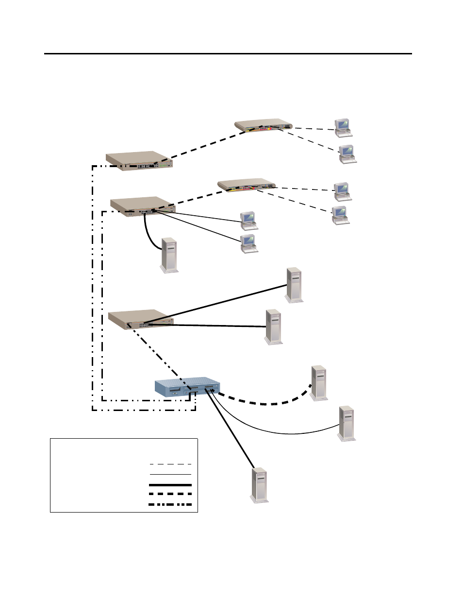
Figure 4-2 shows how the different switches fit into a large corporate
network with a Fast Ethernet infrastructure. A switch is located on
each floor and servers are centralized in one room.
Figure 4-2 Switches in Workgroup Configurations
RS-232
TERMINAL PO
RT
STATUS
10BASE-T / 100
BASE-TX
FAST ETHERNET SW
ITCH
PORT ACTIVITY
10BASE-T / 10
0BASE-TX
AT-FS718 with AT-A11 Fiber uplink
AT-FS718
AT-FS718
Hub
Hub
FORMULA 8200 switch
with TX and FX ports
Legend
Dedicated 10 Mbps link
Dedicated 100 Mbps link
10/100 Mbps link
BACKBONE
Shared 10/100 Mbps link
Workstations
Workstations
Servers
Dedicated 100 Mbps fiber
This manual is related to the following products: