Port leds, Figure15 port leds, Rs232 connector – Allied Telesis AT-FS724 User Manual
Page 16: Reset button, 3ruw#/('v, 5hvhw#%xwwrq
+DUGZDUH#'HVFULSWLRQ
1-6
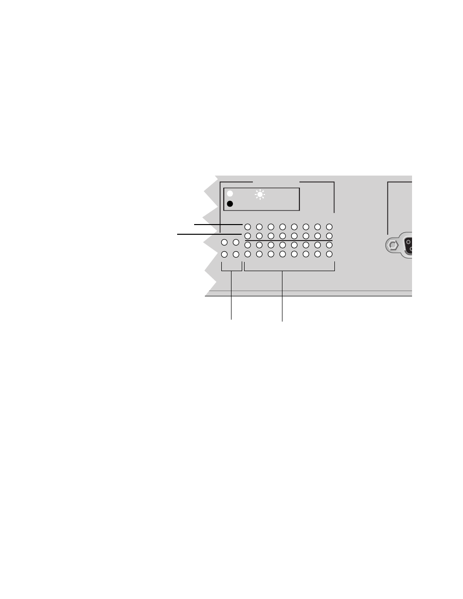
3RUW#/('V
Each switch port and uplink port is associated with two LEDs
indicating the following:
❑
Valid physical link with a device and packets being received, as
indicated by the top row of LEDs
❑
Speed of transmission, 10 Mbps or 100 Mbps, as indicated by
the bottom row of LEDs
Figure 1-5 is a close-up of the AT-FS718 port LEDs. (The
AT-FS724 does not have uplink port LEDs.)
Figure 1-5 Port LEDs
The LEDs are further described in Chapter 2, Table 2-1 on page 2-4.
56565#&RQQHFWRU
The RS232, DB-9 female connector provides for port configuration,
diagnostics or software update via a VT100 terminal emulation using
a straight-through serial cable.
5HVHW#%XWWRQ
The Reset button is used to reset the switch with power still applied.
TERM
PORT ACTIVITY
1
3
5
7
9
11
13
15
2
B
A
4
6
8
10
12
14
16
15X
16X
LINK /
RECEIVE
100M
Link and received packets indicator (green)
Transmission speed indicator (amber)
Uplink port LEDs
Station port LEDs