Figure24 connecting the 50-pin plug, Apply power to the unit as follows – Allied Telesis AT-FS724 User Manual
Page 28
,QVWDOODWLRQ
2-8
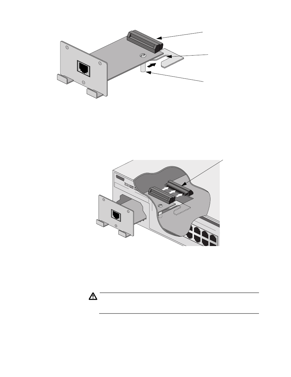
Figure 2-3 Guiding the MDA’s Standoff Into Its Slot
4. Slide the MDA into its empty slot making sure that the standoff is
aligned properly. See Figure 2-3.
5. Push the MDA into position so that the front panel contacts the
front of the switch’s chassis. See Figure 2-4.
Figure 2-4 Connecting the 50-pin Plug
6. Secure the MDA to the front of the switch with the Phillips
flathead screws that came with the MDA package.
7. Apply power to the unit as follows:
Caution
The power cord is used as a disconnect device. To de-energize
equipment, disconnect the power cord.
'
10
Reattach the power cord to the unit and plug it into the power
source. Verify that the POWER LED lights green.
AT-A10
100B
ASE-TX
X
Standoff
50-pin plug
Slot
POR
T A
100B
ASE-TX
10B
AS
2X
AT-A10
100B
ASE-TX
X
50-pin receptacle