Chapter4, Switch configurations, The switch in a standalone configuration – Allied Telesis AT-FS724 User Manual
Page 47: Chapter 4, Switch configurations,” pr, 6zlwfk#&rqiljxudwlrqv, Kdswhu 7, 7kh#6zlwfk#lq#d#6wdqgdorqh#&rqiljxudwlrq
4-1
#&KDSWHU 7
6ZLWFK#&RQILJXUDWLRQV
This chapter provides network configuration examples using the
switch models described in this guide.
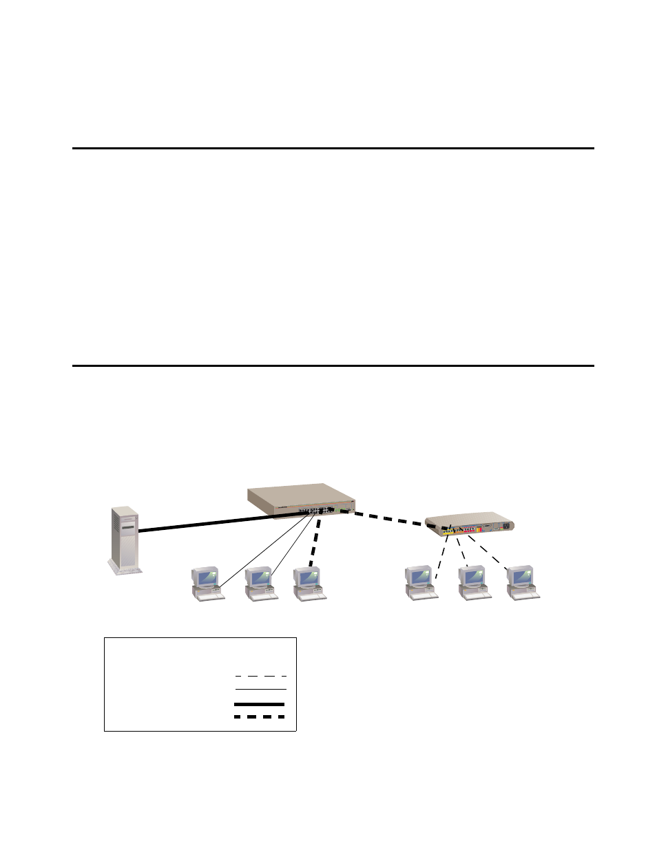
7KH#6ZLWFK#LQ#D#6WDQGDORQH#&RQILJXUDWLRQ
Figure 4-1 shows the AT-FS724 used as a standalone switch for a
group of heavy traffic users. Switching is brought to the desktop
either through a single end-station per switch port or through a
multi-port hub. A 100 Mbps server is connected to a port, providing
end stations high-speed accessibility to its applications.
Figure 4-1 The AT-FS724 Switch in Standalone Configuration
RS-232
TERMINAL PO
RT
STATUS
10BASE-T / 100
BASE-TX
FAST ETHERNET SWITCH
PORT ACTIVITY
10BASE-T / 10
0BASE-TX
AT-FS724
Legend
Dedicated 10 Mbps link
Dedicated 100 Mbps link
10/100 Mbps Hub
10/100 Mbps link
Shared 10/100 Mbps link
Workstations
Workstations
Server