The media dependent adapters (mdas), Figure16 ata10 (tx) and ata11 (fx) mdas, Table12 media dependent adapter features – Allied Telesis AT-FS724 User Manual
Page 18: 7kh#0hgld#'hshqghqw#$gdswhuv#+0'$v
+DUGZDUH#'HVFULSWLRQ
1-8
7KH#0HGLD#'HSHQGHQW#$GDSWHUV#+0'$V,
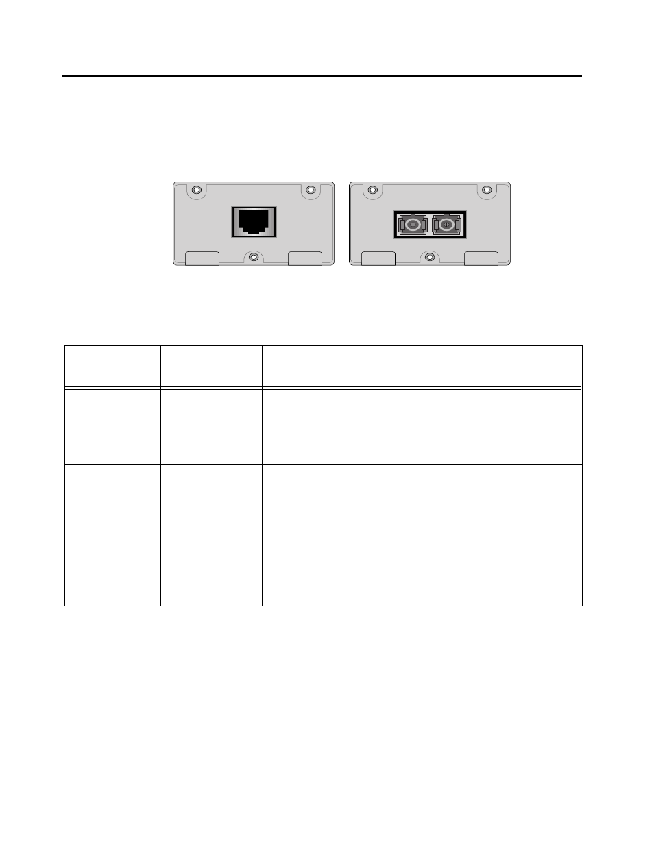
Allied Telesyn offers optional MDAs, shown in Figure 1-6. You may
install either uplink option in one or both Port A or Port B on the
AT-FS718. Table 1-2 describes the MDAs.
Figure 1-6 AT-A10 (TX) and AT-A11 (FX) MDAs
Like the switch’s station ports, the uplink ports are associated with
two LEDs that indicate port speed and valid physical link. See
Figure 1-5 for the location of the uplink ports LEDs. The LEDs are
further described in Chapter 2, Table 2-1 on page 2-4.
AT-A11
100BASE-FX/SC
RX
TX
AT-A10
100BASE-TX
X
Table 1-2 Media Dependent Adapter Features
Adapter
Connector
Type
Description
AT-A10
RJ45
❑
Auto-negotiationg 10Base-T/100Base-TX Fast Ethernet
port
❑
Maximum segment length: 328 ft (100 m), Category 5
UTP cable
AT-A11
Fiber SC
❑
100Base-FX Fast Ethernet port
❑
Default transmission speed fixed at 100 Mbps
❑
Multimode SC fiber connector
❑
Selectable duplex (default full-duplex)
❑
Maximum segment length: 1.25 miles (2 km),
50/125- and 62/5/125-micron multimode fiber cable for
full-duplex; 1,351 ft (412 m) for half-duplex