Spanning tree and vlans – Allied Telesis AT-S86 User Manual
Page 101
AT-S86 Management Software User’s Guide
101
not to activate RSTP on an AT-FS750/48 Fast Ethernet Smart Switch even
when all other switches are running STP. The switch can combine its
RSTP with the STP of the other switches. The switch monitors the traffic
on each port for BPDU packets. Ports that receive RSTP BPDU packets
operates in RSTP mode while ports receiving STP BPDU packets operate
in STP mode.
Spanning Tree
and VLANs
The spanning tree implementation in the AT-S86 management software is
a single-instance spanning tree. The switch supports just one spanning
tree. You cannot define multiple spanning trees.
The single spanning tree encompasses all ports on the switch. If the ports
are divided into different VLANs, the spanning tree crosses the VLAN
boundaries. This point can pose a problem in networks containing multiple
VLANs that span different switches and are connected with untagged
ports. In this situation, STP blocks a data link because it detects a data
loop. This can cause fragmentation of your VLANs.
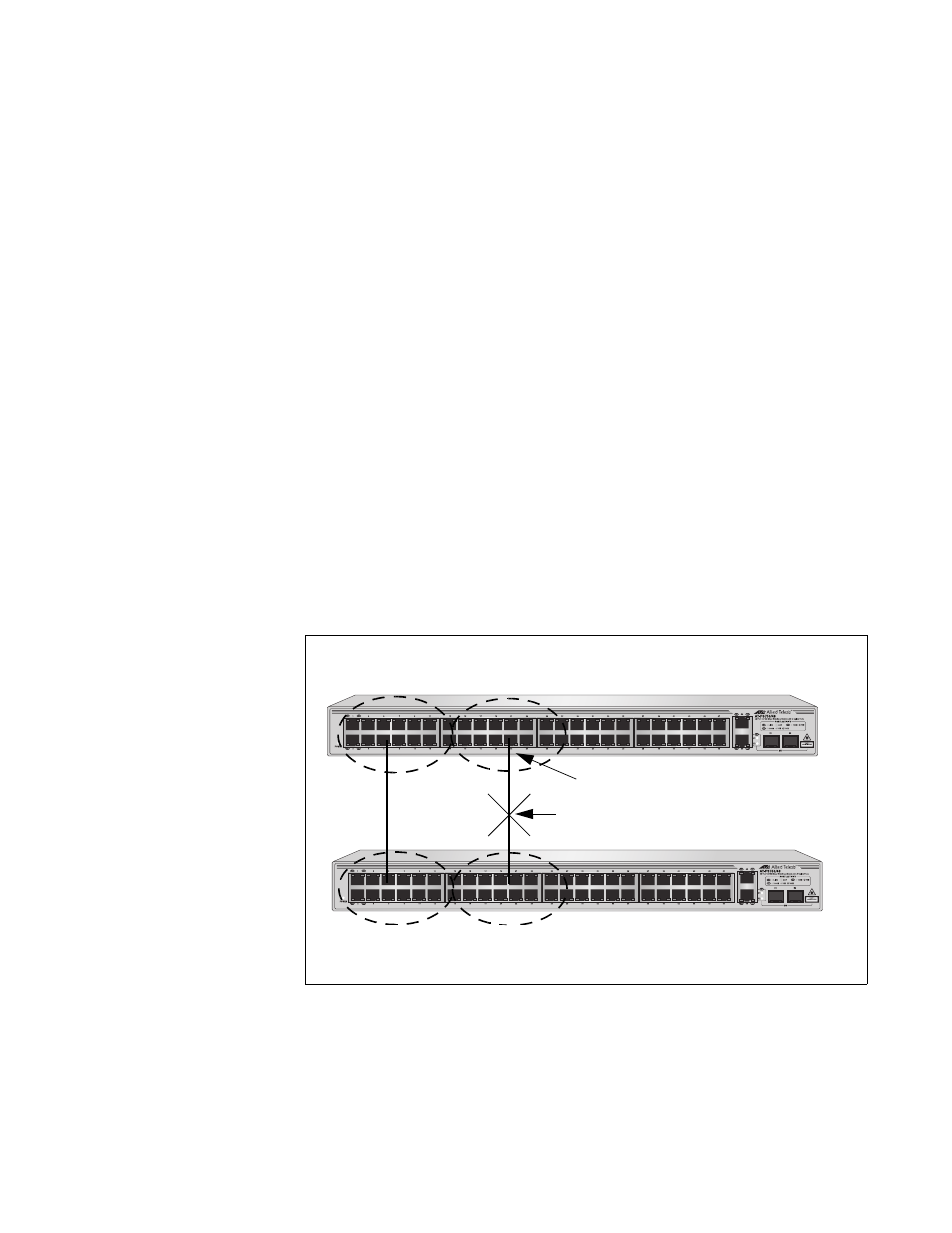
This issue is illustrated in Figure 32. Two VLANs, Sales and Production,
span two AT-FS750/48 Fast Ethernet Smart Switches. Two links
consisting of untagged ports connect the separate parts of each VLAN. If
STP or RSTP is activated on the switches, one of the links is disabled. In
the example, the port on the top switch that links the two parts of the
Production VLAN is changed to the block state. This leaves the two parts
of the Production VLAN unable to communicate with each other.
Figure 32. VLAN Fragmentation
1025
1025
Sales
VLAN
Production
VLAN
Production
VLAN
Sales
VLAN
Blocked Port
Blocked Data Link