Allied Telesis AT-9448Ts/XP (Basic Layer 3) User Manual
Page 61
AT-9400Ts Stack Installation Guide
61
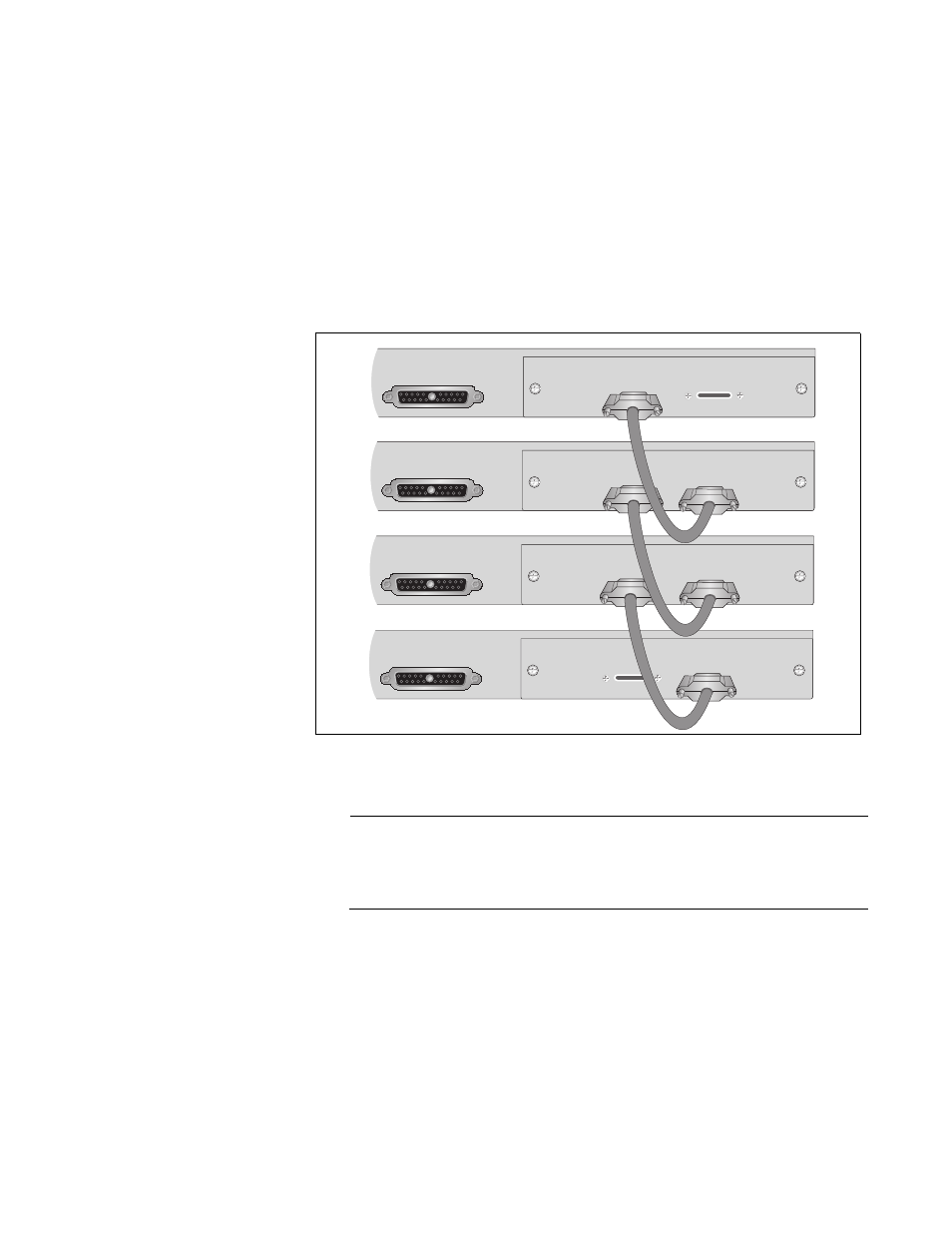
3. Connect the other end of the stacking cable to a Stack Port on the
stacking module in the next switch of the stack. The cable connections
must crossover to a different numbered port on the next stacking
module. Stack Port 1 on a module must connect to Stack Port 2 on
another module. Do not connect two Stack Port 1 ports or Stack Port 2
ports together.
4. Repeat steps 1, 2, and 3 to cable the remaining switches of the stack
with the AT-StackXG/.5 Stacking Cables. Figure 26 illustrates the
cabling configuration for a stack of four switches.
Figure 26. Example of a Cabling Configuration for a Stack with Four
Switches
Note
If you purchased the optional AT-StackXG/1 Stacking Cable,
continue with this procedure to install it. Otherwise, go to the next
procedure to power on the switches.
5. After removing the plastic protectors from the connectors on the
AT-StackXG/1 Stacking Cable as shown in Figure 24 on page 60,
connect the cable to the unused Stack Ports on the top and bottom
switches of the stack. The connections must crossover with the cable
connecting to different numbered ports on the stacking modules.
RPS INPUT
AT-StackXG
STACK PORT 1
STACK PORT 2
RPS INPUT
AT-StackXG
STACK PORT 1
STACK PORT 2
RPS INPUT
AT-StackXG
STACK PORT 1
STACK PORT 2
RPS INPUT
AT-StackXG
STACK PORT 1
STACK PORT 2
1246