Rj-45 twisted pair port pinouts – Allied Telesis AT-9448Ts/XP (Basic Layer 3) User Manual
Page 101
AT-9400Ts Stack Installation Guide
101
RJ-45 Twisted Pair Port Pinouts
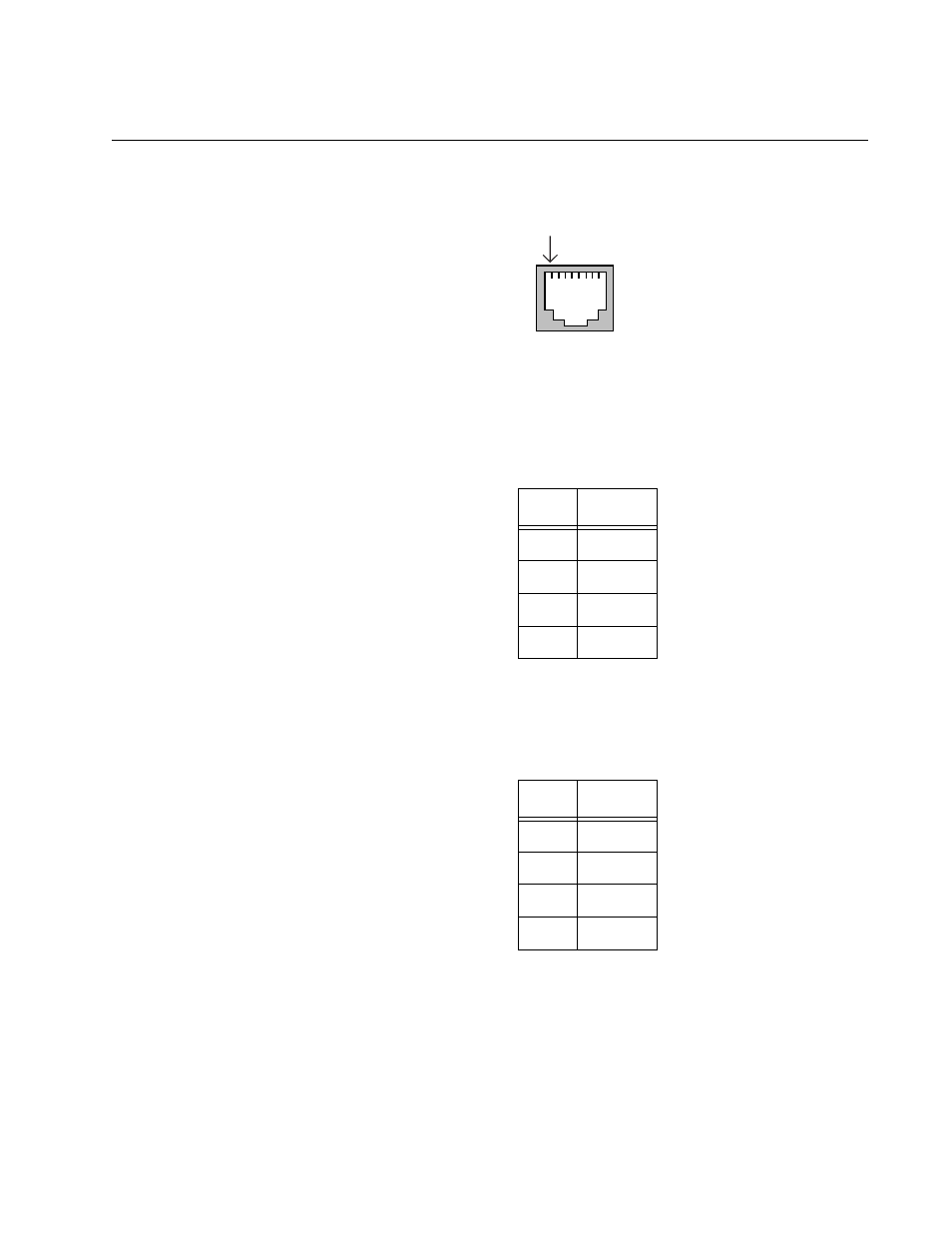
Figure 45 illustrates the pin layout of an RJ-45 connector and port.
Figure 45. RJ-45 Connector and Port Pin Layout
Table 12 lists the pin signals when a port is operating in the MDI
configuration at 10 or 100 Mbps.
Table 13 lists the pin signals when a port is operating in the MDI-X
configuration at 10 or 100 Mbps.
The MDI/MDI-X setting is established automatically when a port is set to
Auto-Negotiation. If a port’s speed and duplex are set manually, the setting
defaults to the MDI-X setting.
Table 12. MDI Pin Signals - 10 or 100 Mbps
Pin
Signal
1
TX+
2
TX-
3
RX+
6
RX-
Table 13. MDI-X Pin Signals - 10 or 100 Mbps
Pin
Signal
1
RX+
2
RX-
3
TX+
6
TX-
Pin 1
This manual is related to the following products: