Cabling an at-x6em/xs2 stacking module, Chapter 3: installing the hardware 94 – Allied Telesis x610 Series Layer 3 User Manual
Page 94
Chapter 3: Installing the Hardware
94
Cabling an
AT-x6EM/XS2
Stacking Module
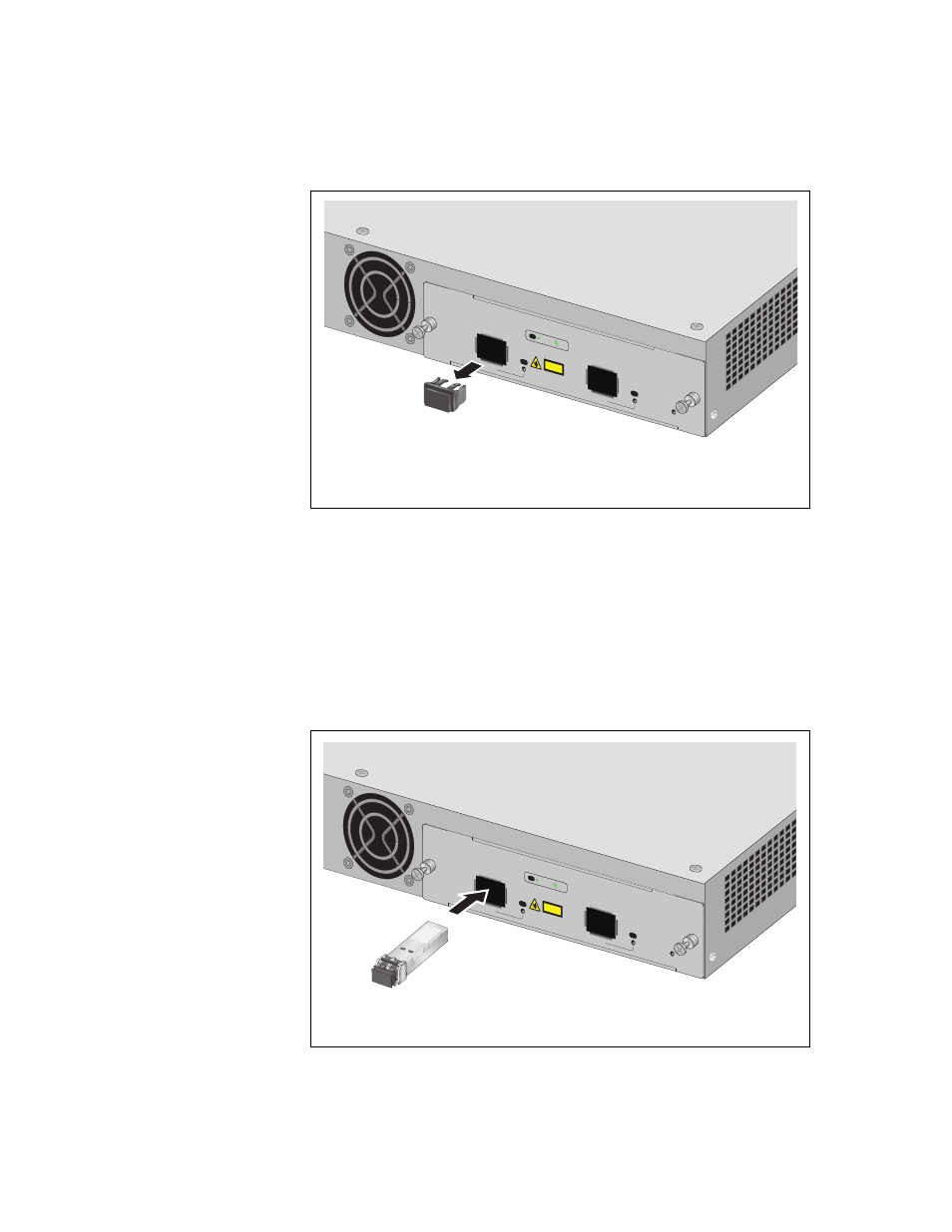
1. Remove the dust plug from a transceiver slot on the switch, as shown
in Figure 64.
RPS
READ
Y
STACK
ING
risk of
rvicing
AT-LX44
CPUCV
R
AT-x6EM/X
S2
1
2
L/A
L/A
POWER
SFP+
SFP+
CLASS 1
LASER P
RODU
CT
10G L
INK
ACT
L/A
RPS
READ
Y
STACKING
risk of
rvicing
AT-LX44CPUCVR
AT-x6EM/X
S2
1
2
L/A
L/A
POWER
SFP+
SFP+
CLASS 1
LASER P
RODUCT
10G LINK
ACT
L/A
Figure 64. Removing a Dust Plug from a SFP+ Slot
2. Remove the transceiver from its shipping container and store the
packaging material in a safe location.
3. Position the transceiver with the label facing up.
4. Slide the transceiver into the slot until it clicks into place, as shown in
Figure 65. Installing an SFP+ Transceiver
See also other documents in the category Allied Telesis Computer hardware:
- AT-GS908M (54 pages)
- AT-x230-10GP (80 pages)
- AT-GS950/48PS (64 pages)
- AT-GS950/10PS (386 pages)
- AT-GS950/16PS (386 pages)
- AT-GS950/48PS (386 pages)
- AT-9000 Series (258 pages)
- AT-9000 Series (1480 pages)
- IE200 Series (70 pages)
- AT-GS950/48 (378 pages)
- AT-GS950/48 (60 pages)
- AT-GS950/48 (410 pages)
- AT-GS950/8 (52 pages)
- SwitchBlade x8106 (322 pages)
- SwitchBlade x8112 (322 pages)
- SwitchBlade x8106 (240 pages)
- SwitchBlade x8112 (240 pages)
- AT-TQ Series (172 pages)
- AlliedWare Plus Operating System Version 5.4.4C (x310-26FT,x310-26FP,x310-50FT,x310-50FP) (2220 pages)
- FS970M Series (106 pages)
- 8100S Series (140 pages)
- 8100L Series (116 pages)
- x310 Series (116 pages)
- x310 Series (120 pages)
- AT-GS950/16 (44 pages)
- AT-GS950/24 (404 pages)
- AT-GS950/24 (366 pages)
- AT-GS950/16 (404 pages)
- AT-GS950/16 (364 pages)
- AT-GS950/8 (404 pages)
- AT-GS950/8 (364 pages)
- AT-GS950/8 (52 pages)
- AT-8100 Series (330 pages)
- AT-8100 Series (1962 pages)
- AT-FS970M Series (330 pages)
- AT-FS970M Series (1938 pages)
- SwitchBlade x3106 (288 pages)
- SwitchBlade x3112 (294 pages)
- SwitchBlade x3106 (260 pages)
- SwitchBlade x3112 (222 pages)
- AT-S95 CLI (AT-8000GS Series) (397 pages)
- AT-S94 CLI (AT-8000S Series) (402 pages)
- AT-IMC1000T/SFP (23 pages)
- AT-IMC1000TP/SFP (24 pages)
- AT-SBx3106WMB (44 pages)