Power supply module installation, Overview – Allied Telesis x610 Series Layer 3 User Manual
Page 81
x610 Series Layer 3 Gigabit Ethernet Switches Installation Guide
81
Power Supply Module Installation
Overview
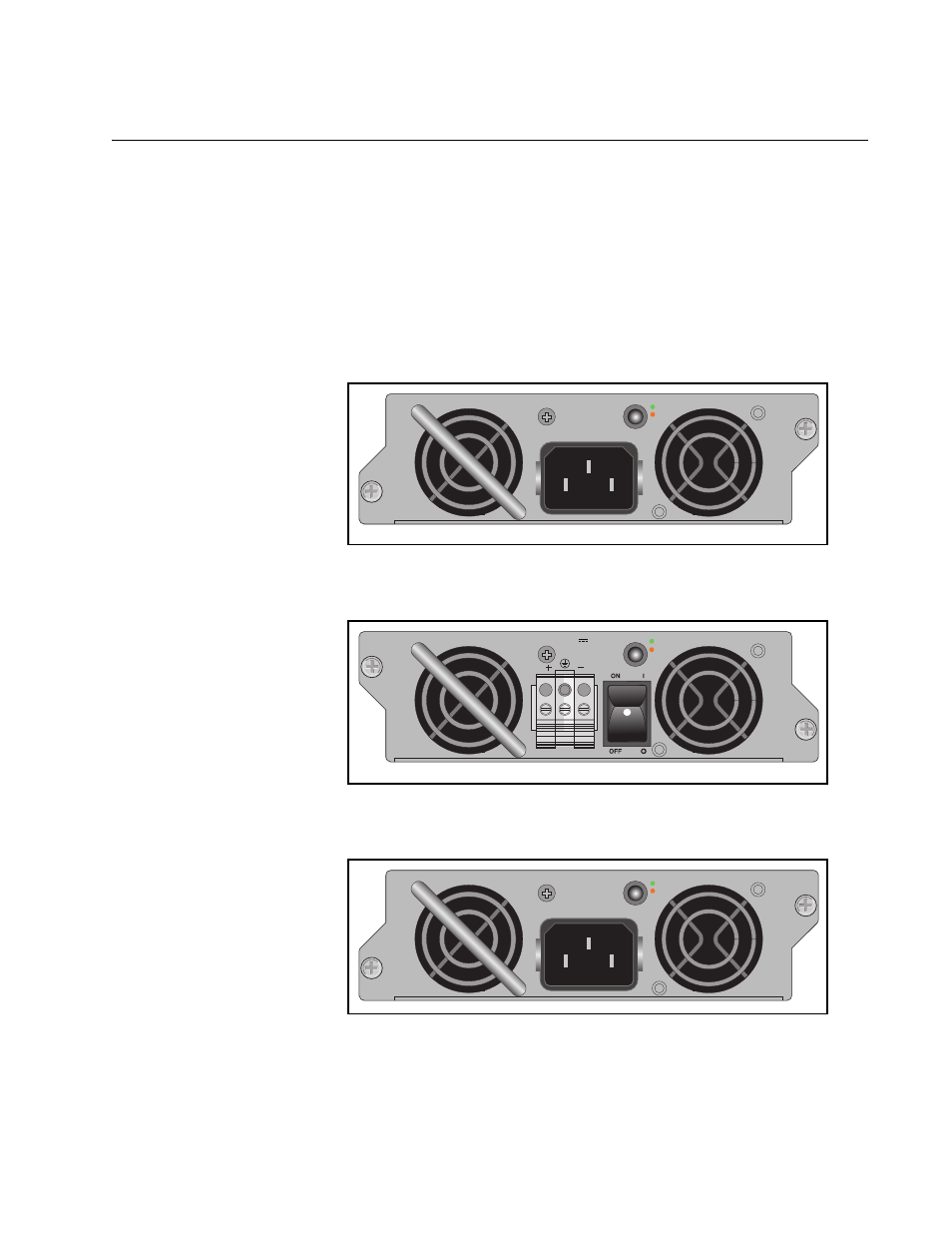
The x610-24Ts-POE+, x610-24Ts/X-POE+, x610-48Ts-POE+ and
x610-48Ts/X-POE+ switches are supplied with a factory installed blank
panel on the power supply slot. Either an AC or DC version of the 250W
(AT-PWR250) power supply shown in Figure 43 and Figure 44, 800W
(AT-PWR800) power supply, shown in Figure 45 on page 81, or a 1200W
(AT-PWR1200) power supply, shown in Figure 46 on page 82, can be
installed in these switches. The installation procedure is identical for each
type of power supply.
100-240VAC~ 5A MAX
DC PWR
FAULT
A
T
-PWR250
2196
2197
FOR CENTRALIZED DC POWER
CONNECTION, INST
ALL ONL
Y IN A
RESTRICTED AREA.
40-60VDC
6A
OUTPUT POWER
FAULT
A
T
-PWR250
100-240VAC~ 12A MAX
DC PWR
FAULT
A
T
-PWR800
Figure 43. AT-PWR250 AC Power Supply
Figure 44. AT-PWR250 DC Power Supply
Figure 45. AT-PWR800 Power Supply
- AT-GS908M (54 pages)
- AT-x230-10GP (80 pages)
- AT-GS950/48PS (64 pages)
- AT-GS950/10PS (386 pages)
- AT-GS950/16PS (386 pages)
- AT-GS950/48PS (386 pages)
- AT-9000 Series (258 pages)
- AT-9000 Series (1480 pages)
- IE200 Series (70 pages)
- AT-GS950/48 (378 pages)
- AT-GS950/48 (60 pages)
- AT-GS950/48 (410 pages)
- AT-GS950/8 (52 pages)
- SwitchBlade x8106 (322 pages)
- SwitchBlade x8112 (322 pages)
- SwitchBlade x8106 (240 pages)
- SwitchBlade x8112 (240 pages)
- AT-TQ Series (172 pages)
- AlliedWare Plus Operating System Version 5.4.4C (x310-26FT,x310-26FP,x310-50FT,x310-50FP) (2220 pages)
- FS970M Series (106 pages)
- 8100S Series (140 pages)
- 8100L Series (116 pages)
- x310 Series (116 pages)
- x310 Series (120 pages)
- AT-GS950/16 (44 pages)
- AT-GS950/24 (404 pages)
- AT-GS950/24 (366 pages)
- AT-GS950/16 (404 pages)
- AT-GS950/16 (364 pages)
- AT-GS950/8 (404 pages)
- AT-GS950/8 (364 pages)
- AT-GS950/8 (52 pages)
- AT-8100 Series (330 pages)
- AT-8100 Series (1962 pages)
- AT-FS970M Series (330 pages)
- AT-FS970M Series (1938 pages)
- SwitchBlade x3106 (288 pages)
- SwitchBlade x3112 (294 pages)
- SwitchBlade x3106 (260 pages)
- SwitchBlade x3112 (222 pages)
- AT-S95 CLI (AT-8000GS Series) (397 pages)
- AT-S94 CLI (AT-8000S Series) (402 pages)
- AT-IMC1000T/SFP (23 pages)
- AT-IMC1000TP/SFP (24 pages)
- AT-SBx3106WMB (44 pages)