Installing a vcstack stacking module, At -pwr1200 – Allied Telesis x610 Series Layer 3 User Manual
Page 82
100-240VAC~ 16A MAX
DC PWR
FAULT
A
T
-PWR1200
2267
Chapter 3: Installing the Hardware
82
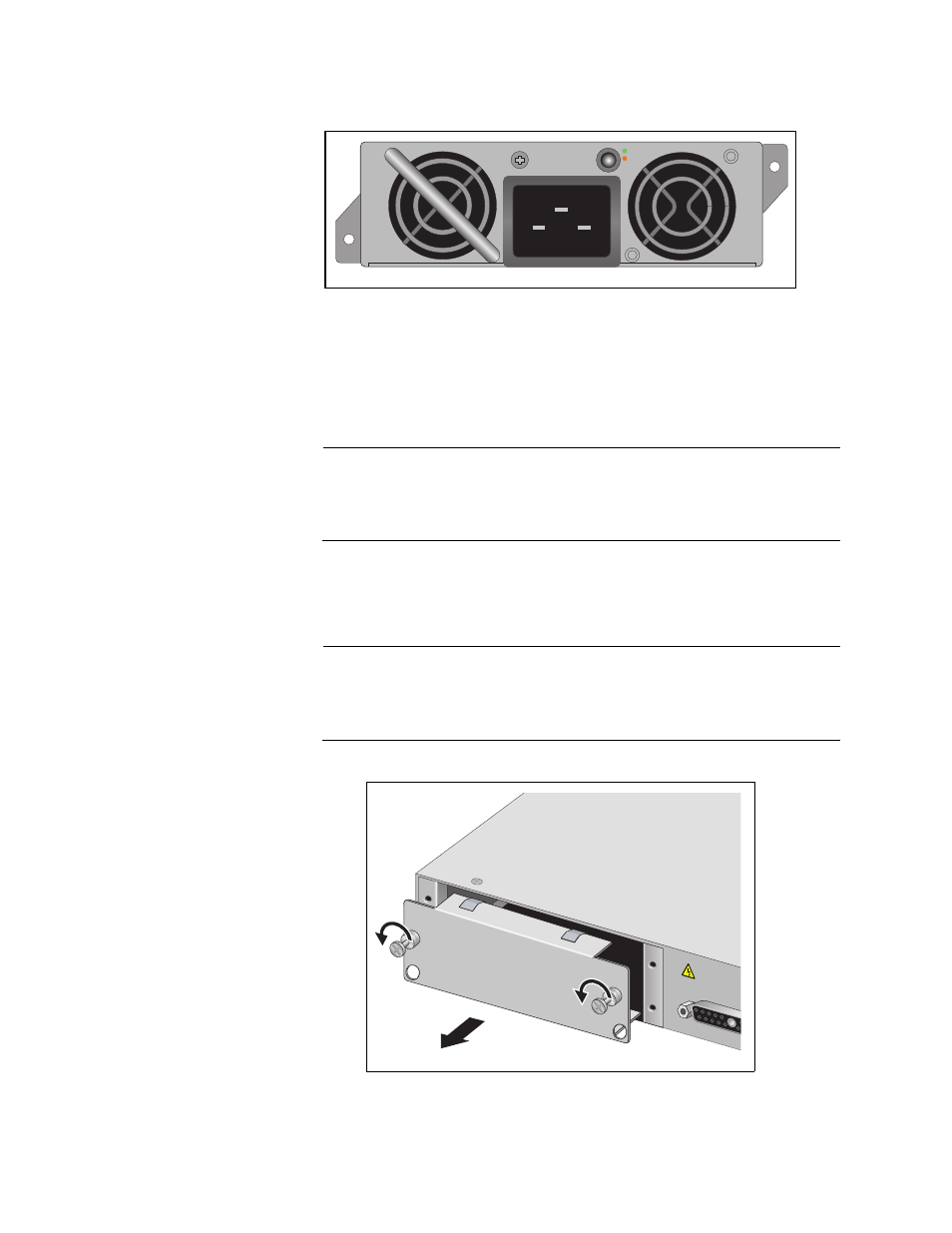
Figure 46. AT-PWR1200 Power Supply
Installing a
VCStack
Stacking Module
To install a power supply into a POE chassis, perform the following
procedure:
1. Remove the module from the shipping package.
2330
PO
WER
S
UPPL
Y
RPS I
56V/18A MAX
WARNING
This un
it may h
ave more
electric
shock, discon
ne
unit.
AT-LX4
4CPUCV
R
Note
Store the packaging material in a safe location. You must use the
original shipping material if you need to return the unit to Allied
Telesis.
2. Remove the blank panel from the power supply slot on the rear panel
of the switch by loosening the two captive screws on the panel with a
cross-head screwdriver, as shown in Figure 47.
Note
The x610-24Ts-POE+, x610-24Ts/X-POE+, x610-48Ts-POE+ and
x610-48Ts/X-POE+ switch chassis are shipped from the factory with
a blank panel installed in the rear panel power supply slot.
Figure 47. Removing the Blank Panel from the Power Supply Slot
- AT-GS908M (54 pages)
- AT-x230-10GP (80 pages)
- AT-GS950/48PS (64 pages)
- AT-GS950/10PS (386 pages)
- AT-GS950/16PS (386 pages)
- AT-GS950/48PS (386 pages)
- AT-9000 Series (258 pages)
- AT-9000 Series (1480 pages)
- IE200 Series (70 pages)
- AT-GS950/48 (378 pages)
- AT-GS950/48 (60 pages)
- AT-GS950/48 (410 pages)
- AT-GS950/8 (52 pages)
- SwitchBlade x8106 (322 pages)
- SwitchBlade x8112 (322 pages)
- SwitchBlade x8106 (240 pages)
- SwitchBlade x8112 (240 pages)
- AT-TQ Series (172 pages)
- AlliedWare Plus Operating System Version 5.4.4C (x310-26FT,x310-26FP,x310-50FT,x310-50FP) (2220 pages)
- FS970M Series (106 pages)
- 8100S Series (140 pages)
- 8100L Series (116 pages)
- x310 Series (116 pages)
- x310 Series (120 pages)
- AT-GS950/16 (44 pages)
- AT-GS950/24 (404 pages)
- AT-GS950/24 (366 pages)
- AT-GS950/16 (404 pages)
- AT-GS950/16 (364 pages)
- AT-GS950/8 (404 pages)
- AT-GS950/8 (364 pages)
- AT-GS950/8 (52 pages)
- AT-8100 Series (330 pages)
- AT-8100 Series (1962 pages)
- AT-FS970M Series (330 pages)
- AT-FS970M Series (1938 pages)
- SwitchBlade x3106 (288 pages)
- SwitchBlade x3112 (294 pages)
- SwitchBlade x3106 (260 pages)
- SwitchBlade x3112 (222 pages)
- AT-S95 CLI (AT-8000GS Series) (397 pages)
- AT-S94 CLI (AT-8000S Series) (402 pages)
- AT-IMC1000T/SFP (23 pages)
- AT-IMC1000TP/SFP (24 pages)
- AT-SBx3106WMB (44 pages)