Allied Telesis x610 Series Layer 3 User Manual
Page 80
2075
22
SFP
23
21
24
x610-24T
s
-POE+
4
6
8
10
12
3
5
1
2
7
9
11
13
15
17
19
21R
16
18
20
22R
24R
14
23R
1000
/
100
SD
STATUS
FAULT
MASTER
RPS
PWR
PRES
MSTR
L/A
L/A
CLASS 1
LASER P
RODUCT
1
2
STACK
BUSY
READY
FAULT
CON
SOLE
2076
22
SFP
23
21
24
x610-24T
s
-POE+
4
6
8
10
12
3
5
1
2
7
9
11
13
15
17
19
21R
16
18
20
22R
24R
14
23R
1000
/
100
SD
STATUS
FAULT
MASTER
RPS
PWR
PRES
MSTR
L/A
L/A
CLASS 1
LASER P
RODUCT
1
2
STACK
BUSY
READY
FAULT
CON
SOLE
Chapter 3: Installing the Hardware
80
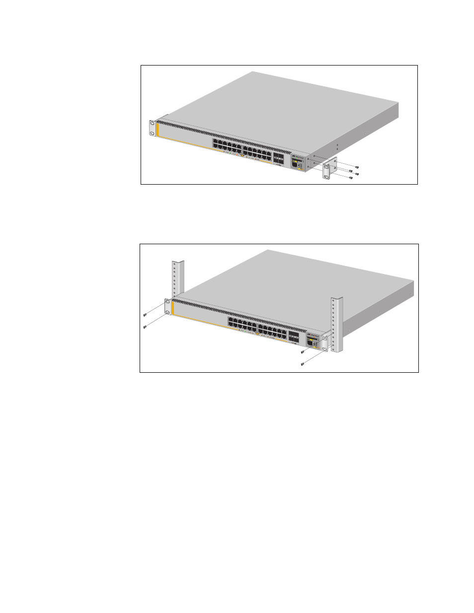
Figure 41. Attaching Rack-Mount Brackets
5. Mount the switch in a 19-inch rack using standard screws (not
provided), as shown in Figure 42.
Figure 42. Mounting the Switch in a Rack
See also other documents in the category Allied Telesis Computer hardware:
- AT-GS908M (54 pages)
- AT-x230-10GP (80 pages)
- AT-GS950/10PS (386 pages)
- AT-GS950/48PS (64 pages)
- AT-GS950/16PS (386 pages)
- AT-GS950/48PS (386 pages)
- AT-9000 Series (1480 pages)
- AT-9000 Series (258 pages)
- IE200 Series (70 pages)
- AT-GS950/48 (410 pages)
- AT-GS950/8 (52 pages)
- AT-GS950/48 (378 pages)
- AT-GS950/48 (60 pages)
- SwitchBlade x8106 (322 pages)
- SwitchBlade x8112 (322 pages)
- SwitchBlade x8106 (240 pages)
- SwitchBlade x8112 (240 pages)
- AT-TQ Series (172 pages)
- AlliedWare Plus Operating System Version 5.4.4C (x310-26FT,x310-26FP,x310-50FT,x310-50FP) (2220 pages)
- FS970M Series (106 pages)
- 8100L Series (116 pages)
- 8100S Series (140 pages)
- x310 Series (120 pages)
- x310 Series (116 pages)
- AT-GS950/24 (404 pages)
- AT-GS950/24 (366 pages)
- AT-GS950/16 (44 pages)
- AT-GS950/16 (364 pages)
- AT-GS950/16 (404 pages)
- AT-GS950/8 (404 pages)
- AT-GS950/8 (364 pages)
- AT-GS950/8 (52 pages)
- AT-8100 Series (330 pages)
- AT-8100 Series (1962 pages)
- AT-FS970M Series (330 pages)
- AT-FS970M Series (1938 pages)
- SwitchBlade x3106 (288 pages)
- SwitchBlade x3112 (294 pages)
- SwitchBlade x3106 (260 pages)
- SwitchBlade x3112 (222 pages)
- AT-S95 CLI (AT-8000GS Series) (397 pages)
- AT-S94 CLI (AT-8000S Series) (402 pages)
- AT-IMC1000T/SFP (23 pages)
- AT-IMC1000TP/SFP (24 pages)
- AT-SBx3106WMB (44 pages)