Installing the dc at-pwr250 power supply module, Chapter 3: installing the hardware 84 – Allied Telesis x610 Series Layer 3 User Manual
Page 84
2268
PO
WER
S
UPPL
Y
RPS I
56V/18A MAX
WARNIN
G
This un
it may h
ave mor
e
electric
shock, d
isconn
e
unit.
FOR CENTRALIZED DC POWER
CONNECTION, INST
ALL ONL
Y IN A
RESTRICTED AREA.
40-60VDC
6A
OUTPU
T POW
ER
FAULT
A
T
-PWR250
2261
PO
WER
S
UPPL
Y
RPS I
56V/18A M
AX
WARNIN
G
This un
it may h
ave m
ore
electric
shock, d
isconne
unit.
100-2
40VAC
~ 12A M
AX
DC PWR
FAULT
A
T
-PWR
8
000
Chapter 3: Installing the Hardware
84
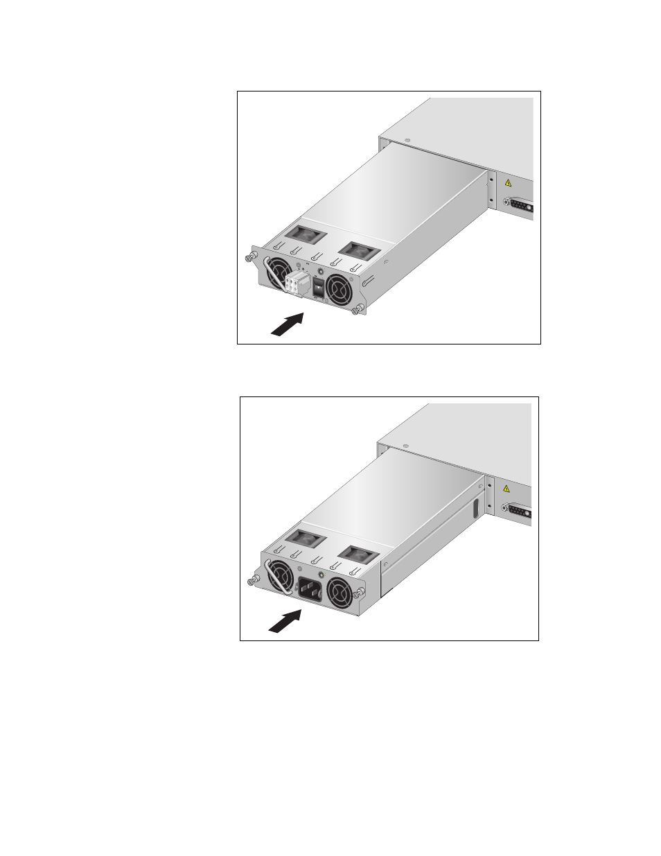
Figure 49. Installing the DC AT-PWR250 Power Supply Module
Figure 50. Installing the AT-PWR800 Power Supply Module
See also other documents in the category Allied Telesis Computer hardware:
- AT-GS908M (54 pages)
- AT-x230-10GP (80 pages)
- AT-GS950/48PS (64 pages)
- AT-GS950/10PS (386 pages)
- AT-GS950/16PS (386 pages)
- AT-GS950/48PS (386 pages)
- AT-9000 Series (258 pages)
- AT-9000 Series (1480 pages)
- IE200 Series (70 pages)
- AT-GS950/48 (378 pages)
- AT-GS950/48 (60 pages)
- AT-GS950/48 (410 pages)
- AT-GS950/8 (52 pages)
- SwitchBlade x8106 (322 pages)
- SwitchBlade x8112 (322 pages)
- SwitchBlade x8106 (240 pages)
- SwitchBlade x8112 (240 pages)
- AT-TQ Series (172 pages)
- AlliedWare Plus Operating System Version 5.4.4C (x310-26FT,x310-26FP,x310-50FT,x310-50FP) (2220 pages)
- FS970M Series (106 pages)
- 8100L Series (116 pages)
- 8100S Series (140 pages)
- x310 Series (116 pages)
- x310 Series (120 pages)
- AT-GS950/24 (404 pages)
- AT-GS950/24 (366 pages)
- AT-GS950/16 (44 pages)
- AT-GS950/16 (404 pages)
- AT-GS950/16 (364 pages)
- AT-GS950/8 (364 pages)
- AT-GS950/8 (52 pages)
- AT-GS950/8 (404 pages)
- AT-8100 Series (330 pages)
- AT-8100 Series (1962 pages)
- AT-FS970M Series (330 pages)
- AT-FS970M Series (1938 pages)
- SwitchBlade x3106 (288 pages)
- SwitchBlade x3112 (294 pages)
- SwitchBlade x3106 (260 pages)
- SwitchBlade x3112 (222 pages)
- AT-S95 CLI (AT-8000GS Series) (397 pages)
- AT-S94 CLI (AT-8000S Series) (402 pages)
- AT-IMC1000T/SFP (23 pages)
- AT-IMC1000TP/SFP (24 pages)
- AT-SBx3106WMB (44 pages)