Allied Telesis x610 Series Layer 3 User Manual
Page 104
2205
A
A
A
T
-PWR250
DC OUT
FAULT
+
-
6A
40-60VDC
FOR CENTR
ALIZED DC POWER
C
ONNECTION,
INST
ALL ONL
Y IN A
ON
OFF
+48 VDC Positive
Ground
-48 VDC Negative
Terminal
Terminal
Terminal
8mm ±1mm
(0.31in. ±0.039in.)
Chapter 4: Cabling the Network Ports
104
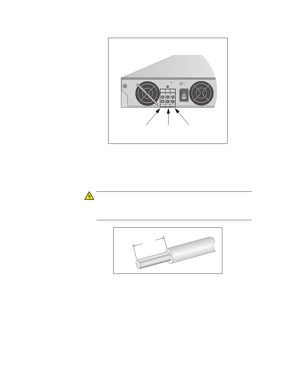
Figure 71. DC Terminal Block on the DC AT-PWR250 Power Supply
Module
4. With a 14-gauge wire-stripping tool, strip the three wires in the tray
cable coming from the DC input power source to 8mm
± 1mm (0.31 in.,
± 0.039 in.), as shown in Figure 72 on page 104.
Warning
Do not strip more than the recommended amount of wire. Stripping
more than the recommended amount can create a safety hazard by
leaving exposed wire on the terminal block after installation. E10
Figure 72. Stripped Wire
5. Insert the power supply ground wire into the middle connector of the
DC terminal and tighten the connection with a flathead screwdriver, as
shown in Figure 73 on page 105.
- AT-GS908M (54 pages)
- AT-x230-10GP (80 pages)
- AT-GS950/48PS (64 pages)
- AT-GS950/10PS (386 pages)
- AT-GS950/16PS (386 pages)
- AT-GS950/48PS (386 pages)
- AT-9000 Series (258 pages)
- AT-9000 Series (1480 pages)
- IE200 Series (70 pages)
- AT-GS950/48 (378 pages)
- AT-GS950/48 (60 pages)
- AT-GS950/48 (410 pages)
- AT-GS950/8 (52 pages)
- SwitchBlade x8106 (322 pages)
- SwitchBlade x8112 (322 pages)
- SwitchBlade x8106 (240 pages)
- SwitchBlade x8112 (240 pages)
- AT-TQ Series (172 pages)
- AlliedWare Plus Operating System Version 5.4.4C (x310-26FT,x310-26FP,x310-50FT,x310-50FP) (2220 pages)
- FS970M Series (106 pages)
- 8100L Series (116 pages)
- 8100S Series (140 pages)
- x310 Series (116 pages)
- x310 Series (120 pages)
- AT-GS950/24 (404 pages)
- AT-GS950/24 (366 pages)
- AT-GS950/16 (44 pages)
- AT-GS950/16 (404 pages)
- AT-GS950/16 (364 pages)
- AT-GS950/8 (364 pages)
- AT-GS950/8 (52 pages)
- AT-GS950/8 (404 pages)
- AT-8100 Series (330 pages)
- AT-8100 Series (1962 pages)
- AT-FS970M Series (330 pages)
- AT-FS970M Series (1938 pages)
- SwitchBlade x3106 (288 pages)
- SwitchBlade x3112 (294 pages)
- SwitchBlade x3106 (260 pages)
- SwitchBlade x3112 (222 pages)
- AT-S95 CLI (AT-8000GS Series) (397 pages)
- AT-S94 CLI (AT-8000S Series) (402 pages)
- AT-IMC1000T/SFP (23 pages)
- AT-IMC1000TP/SFP (24 pages)
- AT-SBx3106WMB (44 pages)