Duro-t, Preliminary remarks, Description – ROHM SUPER-LOCK User Manual
Page 9
9
Preliminary remarks:
1. This operating manual is created under considera-
tion of DIN EN ISO 1100-1, DIN EN ISO 1100-
and the corresponding respective norms.
. For different tool clamping, the necessary force
transfer or moments for the necessary clamping
force is to be determined according to the VDI
guideline 3106 (compare VDMA guideline 34181).
The authorised speeds may also need to be adapted
accordingly.
3. This operating manual applies to all nominal sizes of
the locking unit. Assembly drawings and parts lists
for the individual nominal sizes can be requested
separately from the company RÖHM.
1. Description
1.1 Configuration and functional features
The “SuperLock” locking unit is part of an automatic
HSK tool clamping system. It serves the purpose of
transferring traction to the HSK clamping set and the
subsequent self-locking detent and maintaining the
clamping force. The standard version of the locking unit
is provided with a draw bolt extension on which a clam-
ping and release unit transfers the clamping and release
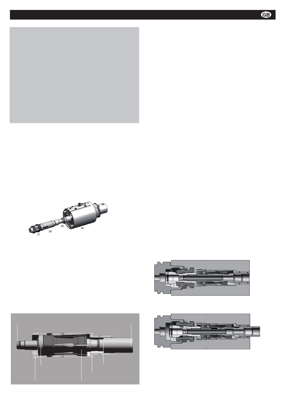
forces or clamping and release strokes (illustration 1).
Illustration 1: Complete unit for automatic HSK tension with HSK
clamping set (1), locking unit (2), pull bolt extension (3), clamp and
release unit (4)
The „SuperLock“ locking unit consists of the collet,
draw bolt, clamping sleeve, draw bar and guide
sleeve (illustration ). It is delivered as a complete
module which is fully assembled. The inserted pull
bolt is removed for installation (compare installation
and assembly). The remaining parts of the SuperLock
module may not be independently dismantled and
assembled.
Illustration 2: configuration of the “SuperLock” locking unit
After assembly of the locking unit, the pressure head
of the HSK clamping set is screwed together with
the draw bar of the locking unit. The draw bolt of the
locking unit are connected with an original Röhm
draw bolt extension, or an operating rod designed
specifically for the customer, to the shaft end during
assembly of the system.
The draw bar of the locking unit generally has a cen-
tral, sealed through-hole for the internal supply of the
medium. The use of this drill hole is only possible for
size HSK25 with a fitted pressure head on the HSK25
clamping set. The clamping sets of the other HSK no-
minal sizes (HSK3-HSK15) have through-holes for
the supply of the medium and can be combined with
the “SuperLock” locking unit without any additional
measures.
In the release position (illustration 3), the draw bolt is
driven up to the draw bar and the pressure head is in
the ejection position for releasing the HSK tool.
The clamping position (illustration 4) is achieved by
applying force to the draw bolts (draw bolt extension)
whereby the self-locking effect exists between the
male taper of the draw bolt and the female taper of
the collet. After reaching the clamping position, a
force application element (e.g. hydraulic piston) brings
the clamping and release unit back to a neutral positi-
on in which the draw bolt extension can freely rotate.
The clamping and release unit is to be designed so
that the stipulated clamping strokes and clamping
forces can be achieved. Particular attention is to be
paid to the possible clamping stroke range caused by
the tolerance of the HSK tools (also refer to assembly/
dismantling).
•
•
•
•
•
Illustration 3: release position of a locking unit with HSK
clamping set
Illustration 4: clamping position of the locking unit with HSK
clamping set
Montage- und Betriebsanleitung für
Fremdsprachentexte ...
Handspannfutter (Keilstangenprinzip)
Fremdsprachentexte ...
Fremdsprachentexte ...
mit Backensicherung
DURO-T
E
F
RUSS
Connection for HSK clamping set
Connection for operating rod
Connection rod
Clamping sleeve
Collet
Guide sleeve
Pull bolt