Duro-t, Overview of forces and strokes of the locking unit – ROHM SUPER-LOCK User Manual
Page 10
10
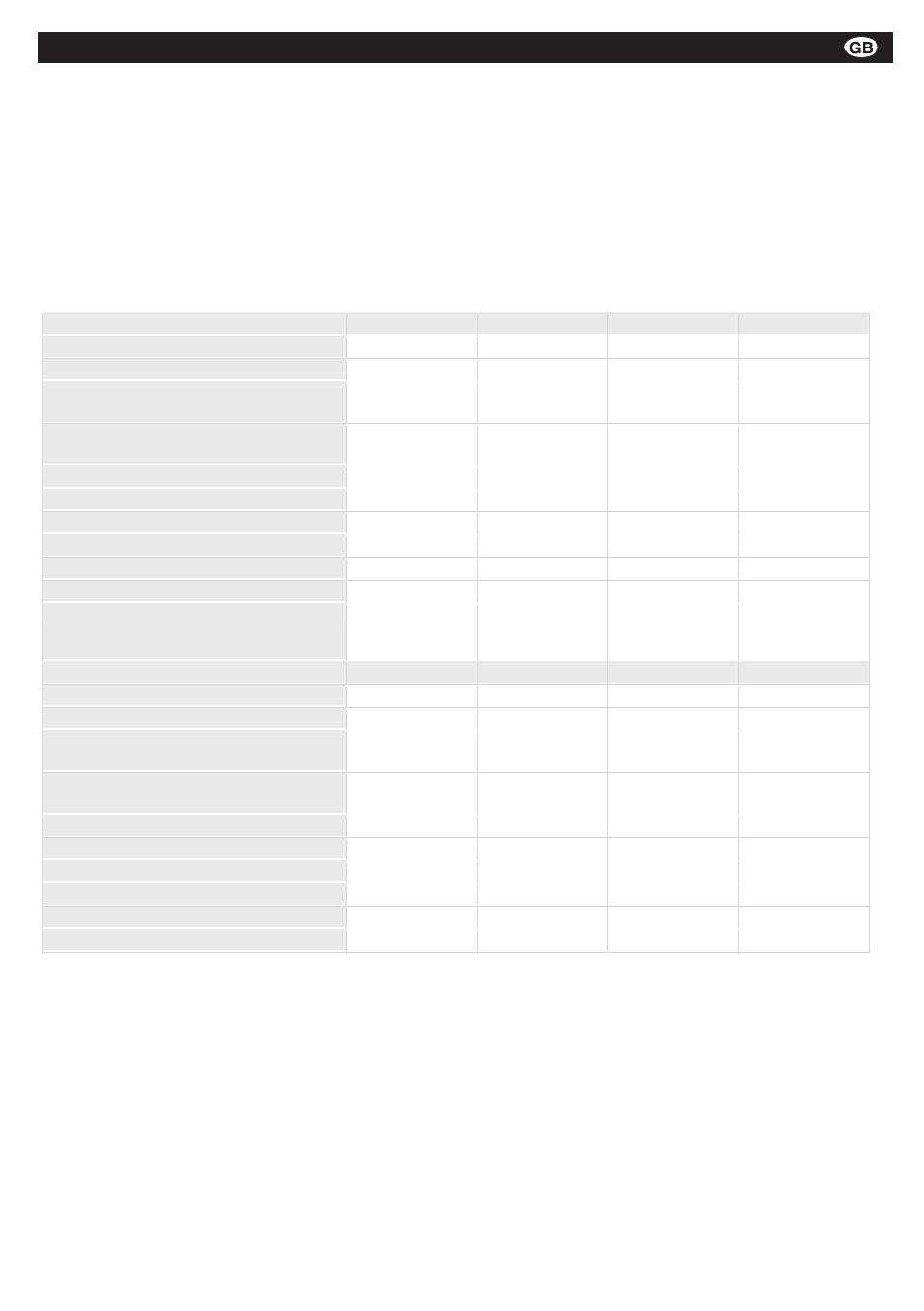
Overview of forces and strokes of the locking unit
The stipulated operating forces on the pull bolt in the
above table are to be achieved to comply with the
draw-in force on the HSK shaft. The application of the
locking unit with lower or higher operating forces on the
pull bolt may not take place independently and must be
coordinated with Röhm in writing.
The locking unit works with a wide tolerance or stroke
range (table 1). This allows the safe locking of the
system with HSK tools which exceed or do not achieve
the stipulated tolerances of the clamping shoulder.
Table 1
1.2 Locking unit functional data
The locking unit may only be applied in connection with
a Röhm HSK clamping set. Any other applications will
be subjected to a technical test by Röhm.
The locking unit is used to save and maintain the
traction in cooperation with an HSK clamping set. Table
1 contains the forces and strokes for the HSK clamping
set and for the actual locking unit. The forces and
strokes of the HSK clamping set can be determined on
a shaft or socket from the front. The forces on the draw
bolt are initialised with a clamping and release unit. The
draw bolt stroke is measured on a draw bolt extension
on the shaft end.
******************************************************************************************* Page: 5
“SuperLock” Locking Unit
Date: 30th April 2009
RN-1701
**********************************************************************************************************
GmbH, Heinrich-Röhm-Str. 50, 89567 Sontheim/Brz., GERMANY, Tel. (49)7325/16-0
Table 1: overview of forces and strokes of the locking unit
The stipulated operating forces on the pull bolt in the above table are to be achieved to comply with
the draw-in force on the HSK shaft. The application of the locking unit with lower or higher operating
forces on the pull bolt may not take place independently and must be coordinated with Röhm in
writing.
The locking unit works with a wide tolerance or stroke range (table 1). This allows the safe locking of
the system with HSK tools which exceed or do not achieve the stipulated tolerances of the clamping
shoulder.
HSK-A/E 25
HSK-A/E 32
HSK-A/E 40
HSK-A/E 50
Draw-in force (HSK clamping force)
3,500 N
5,000 N
10,000 N
15,000 N
Release force (HSK shaft)
ca. 700 N
ca. 1,000 N
ca. 2,000 N
ca. 3,000 N
Nominal clamping stroke (on HSK
clamping set)
4.0 mm
5.5
7.0 mm
8.0 mm
Clamping range (on HSK clamping
set)
3.0-5.0 mm
4.5-6.5 mm
5.5-8.5
6.5-9.5
Ejection stroke
0.2 mm
0.4 mm
0.5 mm
0.5 mm
Operating force on draw bolt
700 N
1,000 N
2,000 N
3,000 N
Nominal clamping stroke on draw bolt
10.8 mm
13.6 mm
17.8 mm
19.9 mm
Stroke range on draw bolt
8.8-12.8 mm
11.6-15.6 mm
14.8-20.8 mm
16.9-22.9 mm
Draw bolt stroke without tool
max. 15.6 mm max. 18.9 mm
max. 22.8 mm max. 26.3 mm
HSK-A/E 63
HSK-A/E 80
HSK-A/E 100
HSK-A/E 125
Draw-in force (HSK clamping force)
25,000 N
37,500 N
50,000 N
70,000 N
Release force (HSK shaft)
ca. 5,000 N
ca. 7,500 N
ca. 10,000 N
ca. 14,000 N
Nominal clamping stroke (on HSK
clamping set)
8.0 mm
11.0 mm
12.0 mm
14.0 mm
Clamping range (on HSK clamping
set)
6.0-10.0
9.0-13.0 mm
10.0-14.0 mm
11.5-16.5 mm
Exhaust stroke
0.5 mm
0.5 mm
0.8 mm
0.8 mm
Operating force on pull bolt
5,000 N
7,500 N
10,000 N
15,000 N
Nominal clamping stroke on pull bolt
20.0 mm
27.3 mm
30.8 mm
37.6 mm
Stroke range on pull bolt
16.0-24.0 mm
23.3-31.3 mm
26.8-34.8 mm
32.6-42.6 mm
Pull bolt stroke without tool
max. 28.0 mm max. 38.1 mm max. 42.4 mm max. 50.8 mm
Montage- und Betriebsanleitung für
Fremdsprachentexte ...
Handspannfutter (Keilstangenprinzip)
Fremdsprachentexte ...
Fremdsprachentexte ...
mit Backensicherung
DURO-T
E
F
RUSS