Duro-t – ROHM SUPER-LOCK User Manual
Page 12
1
3. Assembly, initialisation and dismantling
3.1 Assembly
3.1.1. Order of assembly
3.1.1.1 Draw bolt
In order to install the “SuperLock” locking unit, the first
step is to “pull out” the draw bolt from the complete mo-
dule which has been supplied fully mounted. The draw
bolt must then be installed in the spindle (receiver). It is
preferable to screw the draw bolt outside of the spindle
with the draw bolt extension (with an Allen wrench on
the head of the draw bolt - refer to table below for key
width). The mounting of the draw bolt can also be carried
out from the front with a standard sleeve socket wrench
and extension. The respective torque for the draw bolt is
also contained in table .
The draw bolt extension is inserted into the spindle from
the back and secured to the spindle depending upon the
individual construction of the spindle.
3.1.1.2 Clamping/release units and draw bolt
The next step is to mount the clamping and release unit.
In the release position, the position of the head end of
the draw bolt is measured in the spindle (illustration 5,
table , dimensions l1). Corrections to the position of the
draw bolt can only be undertaken on the clamping and
release unit or the draw bolt extension.
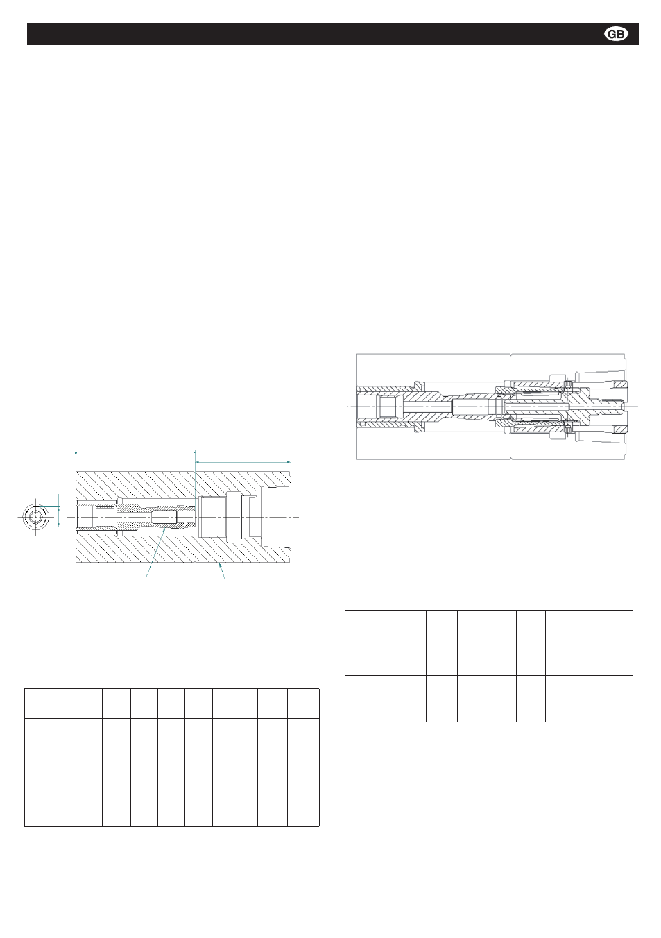
Illustration 5: control dimensions for the installation of the draw bolt
(l1), key width on the draw bolt (SW)
HSK nominal
size:
5
3
40
50
63 80
100
15
Key width on
the draw bolt
(SW):
6,35
8
10
1
15 19
8
Draw bolt tor-
que Mz (Nm):
5
10
0
40
80 150 50
400
Draw bolt-HSK
contact face l1
(mm):
30,4 36,5 47,5 56, 7 93,1 117,8 145,1
Key width (SW), torque (Mz) and control dimensions
for the draw bolt (l1)
3.1.1.3 Locking unit
First of all, the guide sleeve of the locking unit is inserted
in the spindle. Attention should be paid to the careful in-
sertion of the O-ring on the guide sleeve into the spindle
drill hole in order to avoid the shearing of the O-ring.
The module with clamping sleeve, collet and draw bar
is screwed into the spindle from the front. The movable,
protuding collet in the clamping sleeve is initially positi-
oned over the pull bolt without any screwing movement.
The collet is then manually placed on the head of the
draw bolt, the clamping sleeve is repositioned on the
collet as far as it will go on the rotation prevention screw
and is then pushed axial onto the draw bolt (compare
illustration 6) with some pressure. Depending upon
the HSK nominal size, this process is undertaken with
some application of force due to the spread of the collet.
Standard tools can be used as aids.
Assembly position
HSK nominal
size:
5
3
40
50
63
80
100 15
Röhm ID no
for mounting
wrench
117346 1143355 117611 1176114 117348 1176116 1176118 117610
Clamping
sleeve
torque Mh
(Nm)
15
5
35
50
70
95
15 160
Mounting wrench and torque for mounting the
clamping sleeve
Illustration 6: position of the collet in the clamping sleeve during
assembly of the draw bolt.
Once the collet has taken position on the draw bolt and
can be freely turned, the clamping sleeve can be scre-
wed in with a mounting wrench. The mounting wrench
required and the torque for the clamping sleeve are
included in table 3.
Table 2
Table 3
Montage- und Betriebsanleitung für
Fremdsprachentexte ...
Handspannfutter (Keilstangenprinzip)
Fremdsprachentexte ...
Fremdsprachentexte ...
mit Backensicherung
DURO-T
E
F
RUSS
Draw bolt
Spindle
l1
SW
0
0