Rogramming, Idden, Front display – Red Lion P16 User Manual
Page 9: 240 °f spsl, Sp-1
6.0 p
rogrAmming
: h
idden
l
oop
HIDDEN LOOP
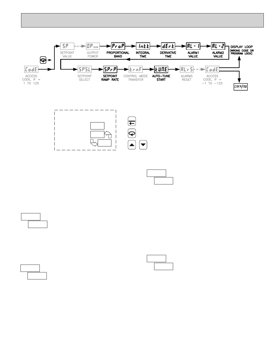
Note: Parameters shown bold are the only parameters visible in the Hidden Loop with Factory Settings. Setpoint and Output Power are
factory set for the Display Loop. The remaining parameters can be selected for the Hidden Loop within Module 3.
Parameter availability is model and programming dependent.
FRONT DISPLAY
ENDS AND RETURNS TO START OF DISPLAY LOOP.
ADVANCES TO NEXT PARAMETER.
CHANGES SELECTION/VALUE.
240
°F
SPSL
TOP DISPLAY
TEMP/PROCESS
BOTTOM DISPLAY
PARAMETER
SELECTION/VALUE
SP-1
F1
To enter Hidden Loop, press A for 3 seconds.
HIDDEN LOOP
When A is pressed and held for three seconds, the controller advances to the
Hidden Loop. The Temperature/Process Value is shown in the top display. The
bottom display alternates between the parameter and its selection/value. B or
J
is pressed to change the selection/value for the shown parameter. The new
selection/value is activated after A is pressed. When L is pressed, the
controller returns to the Display Loop and stores changed selection/values to
permanent memory. Hidden Loop parameters may be locked out in Lockout
Module . Some parameters are model and programming dependent.
1
ACCESS CODE
1
to
12
If the Access Code is set from 1 to 125, in Lockout Module , Access
Code will appear here. By entering the proper Code, access to the Hidden Loop
is permitted. With the factory setting of 0, Access Code will not appear in the
Hidden Loop. A universal code of 111 can be entered to gain access,
independent of the programmed code number.
SETPOINT RAMP RATE
to
nF
CONTROL MODE TRANSFER
SETPOINT SELECT
1
or
2
The SPSL function allows the operator to switch from or to, setpoint 1 and
setpoint 2. In the Display Loop, there is no annunciator indicating the selected
Setpoint, however, the selected Setpoint value is displayed and activated.
In Automatic Mode, the percentage of Output Power is automatically
determined by the controller. In Manual/User Mode, the percentage of
Output Power is adjusted manually while in the Display Loop. The Control
Mode can also be transferred through the F1 Key or User Input. For more
information, see Control Mode Explanations.
The setpoint ramp rate can reduce sudden shock to the process and reduce
overshoot on startup or after setpoint changes, by ramping the setpoint at a
controlled rate. R annunciator flashes while ramping. With the T16, the ramp rate
is always in tenths of degrees per minute, regardless of the resolution chosen for
the process display. With the P16, the ramp rate is in least-significant (display
units) digits per minute. A value of 0.0 or 0 disables setpoint ramping. Once the
ramping setpoint reaches the target setpoint, the setpoint ramp rate disengages
until the setpoint is changed again. If the ramp value is changed during ramping,
the new ramp rate takes effect. If the setpoint is ramping prior to starting Auto-
Tune, the ramping is suspended during Auto-Tune and then resumed afterward.
Deviation and band alarms are relative to the target setpoint, not the ramping
setpoint. A slow process may not track the programmed setpoint rate. At power
up, the ramping setpoint is initialized at the ambient temperature/process value.
9