Output specifications, Ordering information – Red Lion P16 User Manual
Page 3
3
OUTPUT SPECIFICATIONS
1. CONTROL AND ALARM OUTPUTS:
Relay Output:
Type: Form A
Contact Rating: 3 A @ 250 VAC or 30 VDC (resistive load)
Life Expectancy: 100,000 cycles at max. load rating
(Decreasing load and/or increasing cycle time, increases life expectancy)
Logic/SSR Output (main control output only):
Rating: 45 mA max @ 4 V min., 7 V nominal
2. MAIN CONTROL:
Control: PID or On/Off
Output: Time proportioning or DC Analog
Cycle Time: Programmable
Auto-Tune: When selected, sets proportional band, integral time, derivative
time, and output dampening time. Also sets input filter and (if applicable)
cooling gain.
Probe Break Action: Programmable
3. ALARMS: (optional) 2 relay alarm outputs.
Modes:
None
Absolute High Acting (Balanced or Unbalanced Hysteresis)
Absolute Low Acting (Balanced or Unbalanced Hysteresis)
Deviation High Acting
Deviation Low Acting
Inside Band Acting
Outside Band Acting
Heat (Alarm 1 on Analog Output models only)
Cool (Alarm 2)
Reset Action: Programmable; automatic or latched
Standby Mode: Programmable; enable or disable
Hysteresis: Programmable
Sensor Fail Response: Upscale
Annunciator: “A1” and “A2” programmable for normal or reverse acting
4. COOLING: Software selectable (overrides Alarm 2).
Control: PID or On/Off
Output: Time proportioning
Cycle Time: Programmable
Proportional Gain Adjust: Programmable
Heat/Cool Deadband Overlap: Programmable
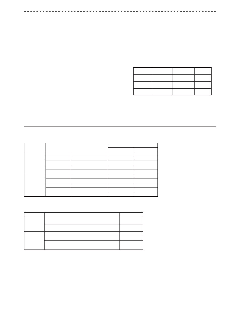
5. ANALOG DC OUTPUT: (optional)
Self-powered (Active)
Action: Control or retransmission
Update Rate: 0.1 to 250 sec
OUTPUT
RANGE **
ACCURACY *
COMPLIANCE
RESOLUTION
0 to 10 V
0.3% of FS
+ ½ LSD
10 kΩ min
1/8000
0 to 20 mA
0.3% of FS
+ ½ LSD
500 Ω max
1/8000
4 to 20 mA
0.3% of FS
+ ½ LSD
500 Ω max
1/6400
* Accuracies are expressed as ± percentages over 0 to 50 °C ambient range
after 20 minute warm-up.
** Outputs are independently jumper selectable for either 10 V or 20 mA. The
output range may be field calibrated to yield approximately 5% overrange
and a small underrange (negative) signal.
ORDERING INFORMATION
MODEL NO.
MAIN CONTROL
2 ALARMS & USER INPUT
PART NUMBERS
18-36 VDC/24 VAC
85 to 250 VAC
T16
Relay
—
T1610010
T1610000
Relay
Yes
T1611110
T1611100
Logic/SSR
—
T1620010
T1620000
Logic/SSR
Yes
T1621110
T1621100
Analog Out *
Yes
T1641110
T1641100
P16
Relay
—
P1610010
P1610000
Relay
Yes
P1611110
P1611100
Logic/SSR
—
P1620010
P1620000
Logic/SSR
Yes
P1621110
P1621100
Analog Out *
Yes
P1641110
P1641100
* Analog out may be used for retransmitted signals. When using analog output for retransmitted signals, AL1
becomes main control O1, if selected for heating in the analog out models.
ACCESSORIES
MODEL NO.
DESCRIPTION
PART NUMBERS
TP16
Programming Kit 1 : Includes Software, Comms Module w/
9-pin connector and cable, and 115 VAC Power Adapter
TP16KIT1
Programming Kit 2 : Includes Software, Comms Module w/
9-pin connector and cable
TP16KIT2
RLY
External SSR Power Unit (for Logic/SSR models)
RLY50000
25 A Single Phase Din Rail Mount Solid State Relay
RLY60000
40 A Single Phase Din Rail Mount Solid State Relay
RLY6A000
Three Phase Din Rail Mount Solid State Relay
RLY70000