1 module 1 - i, T16 o, Type dcpt scal fltr shft splo sphi – Red Lion P16 User Manual
Page 11: Inpt, F1in, Inp cnfp, Nput, Arameters
11
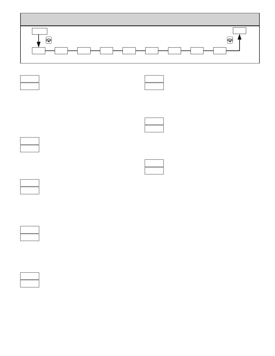
7.1 module 1 - i
nput
p
ArAmeterS
(
1-IN
) t16 o
nly
tYPE
dCPt
SCAL
FLtr
SHFt
SPLO
SPHI
INPUT
TYPE
TEMP
SCALE
DECIMAL
RESOLUTION
DIGITAL
FILTERING
OFFSET
SHIFT/
HIGH LIMIT
SETPOINT
SETPOINT
LOW LIMIT
InPt
INPUT
USER
F1In
F1 KEY
FUNCTION
1-INP
CNFP
PARAMETER MENU
INPUT TYPE
F
TEMPERATURE SCALE
F
Fahrenheit
Celsius
SELECTION TYPE
SELECTION
TYPE
T TC
N TC
E TC
C TC
j
J TC
I
Linear mV
K TC
RTD 385
R TC
2
RTD 392
S TC
2
RTD 672
B TC
I
Linear Ohms
Select the input type that corresponds to the input sensor.
Select either degrees Fahrenheit or Celsius. For linear mV and ohms input
types, this has no effect. If changed, adjust related parameter values, as the
controller does not automatically convert them.
DECIMAL RESOLUTION
to
for temperature and resistance inputs
for mV inputs
Select whole degrees, or tenths of degrees for Temperature display, Setpoint
values, and related parameters. For Linear Resistance inputs I, the same
parameter selections apply in ohms or tenths of an ohm. For mV inputs I,
only hundredths of a mV resolution is available.
SHIFT/OFFSET
to
degrees
This value offsets the controller’s temperature display value by the entered
amount. This is useful in applications in which the sensor cannot provide the
actual temperature signal due to mounting constraints, inaccuracy, etc.
SETPOINT LOW LIMIT
to
The controller has a programmable low setpoint limit value to restrict the
setting range of the setpoint. Set the limit so that the setpoint value cannot be
set below the safe operating area of the process.
I
SETPOINT HIGH LIMIT
to
The controller has a programmable high setpoint limit value to restrict the
setting range of the setpoint. Set the limit so that the setpoint value cannot be
set above the safe operating area of the process.
In
USER INPUT FUNCTION (OPTIONAL)
The controller performs the selected User Input function (User Input
available only on models with alarms), when the User terminal 1 is connected
(pulled low) to Common terminal 8.
No Function: No function is performed.
Program Lock: The Configuration Loop is locked, as long as activated
(maintained action).
Integral Action Lock: The integral action of the PID computation is disabled
(frozen), as long as activated (maintained action).
Auto/Manual Select: This function selects (maintained action) Automatic
(open) or Manual Control (activated).
Setpoint 1 or 2 Select: This function selects (maintained action) Setpoint
1(open) or Setpoint 2 (activated) as the active setpoint.
Setpoint Ramp Disable: The setpoint ramping feature is disabled, as long as
activated (maintained action). Any time the user input is activated with a
ramp in process, ramping is aborted.
Reset Alarms: Active alarms are reset, as long as activated (maintained action).
Active alarms are reset until the alarm condition is cleared and triggered
again (momentary action).
1
F
DIGITAL FILTERING
= least to
= most
The filter is an adaptive digital filter that discriminates between measurement
noise and actual process changes. If the signal is varying too greatly due to
measurement noise, increase the filter value. If the fastest controller response is
needed, decrease the filter value.
SELECTION
FUNCTION
SELECTION
FUNCTION
No Function
Setpoint 1 or 2 Select
Program Lock
Setpoint Ramp Disable
I
Integral Action Lock
Reset Both Alarms
nF
Auto/Manual Select