Uning, Xplanations, 1i f – Red Lion P16 User Manual
Page 22: 11i, 2 n
22
TIME PROPORTIONAL PID CONTROL
In Time Proportional applications, the output power is converted into output
On time using the Cycle Time. For example, with a four second cycle time and
75% power, the output will be on for three seconds (4 × 0.75) and off for
one second.
The cycle time should be no greater than 1/10 of the natural period of
oscillation for the process. The natural period is the time it takes for one
complete oscillation when the process is in a continuously oscillating state.
LINEAR PID CONTROL
In Linear PID Control applications, the Analog Output Assignment is set
to % Output Power, . The Analog Low Scaling, , is set to 0.0 and the
Analog High Scaling, I , is set to 100.0. The Analog Output will then be
proportional to the PID calculated % output power for Heat or Cooling per the
Control Action . For example, with 0 VDC to 10 VDC (scaled 0 to 100%)
and 75% power, the analog output will be 7.5 VDC.
MANUAL CONTROL MODE
In Manual Control Mode, the controller operates as an open loop system
(does not use the setpoint and process feedback). The user adjusts the percentage
of power through the % Power display to control the power for Output O1.
When Alarm 2 is configured for Cooling (O2), Manual operation provides 0 to
100% power to O1 (heating) and -100 to 0% power to O2 (Cooling). The Low
and High Output Power limits are ignored when the controller is in Manual.
MODE TRANSFER
When transferring the controller mode between Automatic and Manual, the
controlling outputs remain constant, exercising true “bumpless” transfer. When
transferring from Manual to Automatic, the power initially remains steady, but
Integral Action corrects (if necessary) the closed loop power demand at a rate
proportional to the Integral Time.
AUTOMATIC CONTROL MODE
In Automatic Control Mode, the percentage of output power is automatically
determined by PID or On/Off calculations based on the setpoint and process
feedback. For this reason, PID Control and On/Off Control always imply
Automatic Control Mode.
p
id
t
uning
e
xplAnAtionS
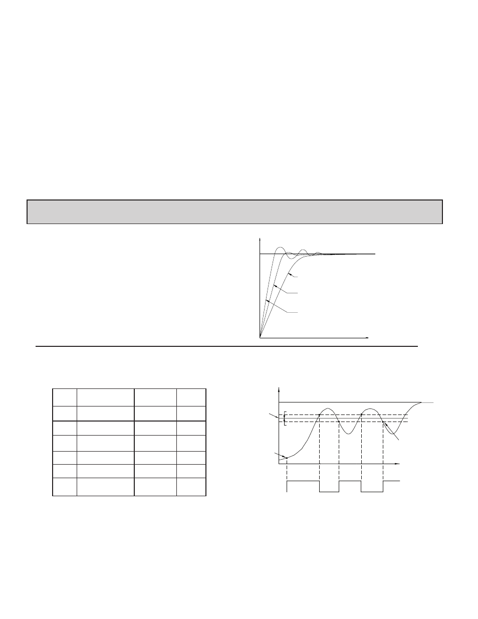
AUTO-TUNE
Auto-Tune is a user-initiated function that allows the controller to
automatically determine the Proportional Band, Integral Time, Derivative Time,
Digital Filter, Control Output Dampening Time, and Relative Gain (Heat/Cool)
values based upon the process characteristics. The Auto-Tune operation cycles
the controlling output(s) at a control point three-quarters of the distance
between the present process value and the setpoint. The nature of these
oscillations determines the settings for the controller’s parameters.
Prior to initiating Auto-Tune, it is important that the controller and system be
first tested. (This can be accomplished in On/Off Control or Manual Control
Mode.) If there is a wiring, system or controller problem, Auto-Tune may give
incorrect tuning or may never finish. Auto-Tune may be initiated at start-up,
from setpoint or at any other process point. However, ensure normal process
conditions (example: minimize unusual external load disturbances) as they will
have an effect on the PID calculations.
TIME
INPUT
TYPICAL RESPONSE CURVES WITH
AUTO-TUNE CODES 0 TO 2.
SP
0
1
2
AUTO-TUNE CODE FIGURE
Start Auto-Tune
Below are the parameters and factory settings that affect Auto-Tune. If these
setting are acceptable then Auto-Tune can be started just by performing two
steps. If changes are needed, then they must be made before starting Auto-Tune.
1. Enter the Setpoint value in the Display Loop.
2. Initiate Auto-Tune by changing Auto-Tune Start to in the Hidden
Loop.
Auto-Tune Progress
The controller will oscillate the controlling output(s) for four cycles. The
bottom display will flash the cycle phase number. Parameter viewing is
permitted during Auto-Tune. The time to complete the Auto-Tune cycles is
process dependent. The controller should automatically stop Auto-Tune and
store the calculated values when the four cycles are complete. If the controller
remains in Auto-Tune unusually long, there may be a process problem. Auto-
Tune may be stopped by entering in Auto-Tune Start .
TIME
INPUT
Aut1
Aut4
AUTO-TUNE
START
AUTO-TUNE
CONTROL
POINT
SETPOINT
AUTO-TUNE COMPLETE, PID
SETTINGS ARE CALCULATED
AND LOADED INTO MEMORY
Aut2
Aut3
ON
OFF
ON
OFF
OUTPUT 1 (O1) :
PHASE
1/2 CHYS *
1/2 CHYS *
* - On/Off Control Hysteresis
AUTO-TUNE OPERATION
(REVERSE ACTING)
DISPLAY
PARAMETER
FACTORY
SETTING
MODULE
Input Type
T16
P16
1I
F
Digital Filtering
1
1I
On/Off Control
Hysteresis
2
T16
2
P16
2
Auto-Tune Code
2
2
Deadband
2
n
Auto-Tune Access