Roubleshooting – Red Lion P16 User Manual
Page 20
20
RESTORE FACTORY SETTINGS
Press and hold B to display . Press A. The controller will display
and then return to F. Press L to return to the Display Loop. This will
overwrite all user settings with Factory Settings.
NOMINAL CALIBRATION SETTINGS
Press and hold B to display . Press A. Press and hold B to display
again. Press A. The controller will then return to F. Press L to
return to the Display Loop. This will not overwrite any user settings but will
erase the controller calibration values. This procedure does not require any
calibration signals nor external meters. This can be used to clear calibration
error flag .
CAUTION: This procedure will result in up to ±10% reading error and the
controller will no longer be within factory specifications. For this reason, this
procedure should only be performed if meter error is outside of this range to
temporarily restore operation until the unit can be accurately calibrated.
For further technical assistance, contact technical support.
t
roubleShooting
Analog Output Calibration (T16 and P16)
Set the controller Analog jumpers to the output type being calibrated.
Connect an external meter with an accuracy of 0.05% (or better) that is capable
of measuring 10.00 V or 20.00 mA to terminals 6 (+V/I) and 7 (-V/I). The
voltage or current calibration that is not being used must be skipped by pressing
A
until End appears.
PROMPT
EXTERNAL
METER
FRONT PANEL ACTION
Press J until
, press A.
Press A.
Press A. (T16 only)
Press A. (T16 only)
Press B for
, press A.
0.00 V
Press B or J until external meter
matches listing, press A.
1
10.00 V
Press B or J until external meter
matches listing, press A.
0.0 mA
Press B or J until external meter
matches listing, press A.
2
20.0 mA
Press B or J until external meter
matches listing, press A.
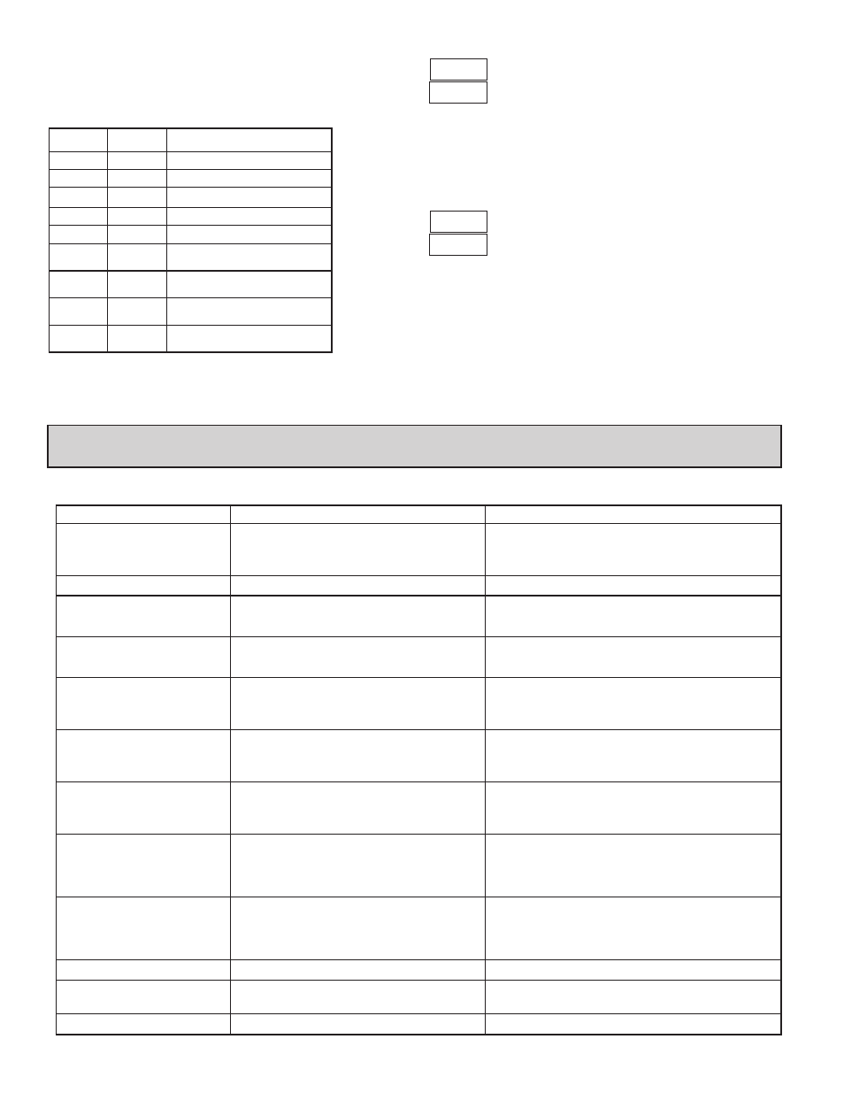
PROBLEM
CAUSE
REMEDIES
NO DISPLAY
1. Power off.
2. Brown-out condition.
3. Loose connection or improperly wired.
4. Bezel assembly not fully seated into rear of controller.
1. Check power.
2. Verify power reading.
3. Check connections.
4. Check installation.
CONTROLLER NOT WORKING
1. Incorrect setup parameters.
1. Check setup parameters.
2
IN DISPLAY
1. Loss of setup parameters due to noise spike or other
EMI event.
1. Press F1 to escape, then check controller accuracy.
a. Recalibrate controller. (See Factory Service Module code 77.)
b. Reset parameters to factory default settings.
IN DISPLAY
1. Loss of calibration parameters due to noise spike or
other EMI event.
1. Press F1 to escape, then check controller accuracy.
a. Recalibrate controller. (See Factory Service Module code 77.)
b. Reset parameters to factory default settings.
or
IN DISPLAY
1. Display value exceeds 4 digit display range.
2. Defective or miscalibrated cold junction circuit.
3. Loss of setup parameters.
4. Internal malfunction.
1. Press F1 to escape, then check controller accuracy.
a. Recalibrate controller. (See Factory Service Module code 77.)
b. Reset parameters to factory default settings.
IN DISPLAY (T16)
1. Probe disconnected.
2. Broken or burned-out probe.
3. Corroded or broken terminations.
4. Excessive process temperature.
1. Change resolution to display whole number and verify reading.
2. Perform cold junction calibration.
3. Check setup parameters.
4. Perform Input calibration.
IN DISPLAY (P16)
1. Input exceeds range of controller.
2. Incorrect input wiring.
3. Defective transmitter.
4. Internal malfunction.
1. Check input parameters.
2. Check input wiring.
3. Replace transmitter.
4. Perform input calibration.
IN TOP DISPLAY
1. Input exceeds range of controller.
2. Temperature exceeds range of input probe.
3. Defective or incorrect transmitter or probe.
4. Excessive high temperature for probe.
5. Loss of setup parameters.
1. Check input parameters.
2. Change to input sensor with a higher temperature range.
3. Replace transmitter or probe.
4. Reduce temperature.
5. Perform input calibration.
IN TOP DISPLAY
1. Input is below range of controller.
2. Temperature below range of input probe.
3. Defective or incorrect transmitter or probe.
4. Excessive low temperature for probe.
5. Loss of setup parameters.
1. Check input parameters.
2. Change to input sensor with a lower temperature range.
3. Replace transmitter or probe.
4. Raise temperature.
5. Perform input calibration.
IN DISPLAY (T16)
1. RTD probe shorted.
1. Check wiring and/or replace RTD probe.
CONTROLLER SLUGGISH OR
NOT STABLE
1. Incorrect PID values.
2. Incorrect probe location.
1. See PID control.
2. Evaluate probe location.
IN DISPLAY
1. Control output is damaged.
1. Return controller to factory for repair.