Etting, Umpers, Nstalling – Red Lion P16 User Manual
Page 5: Ontroller, Multiple controller stacking, Nalog, Utput, Odels
5
1.0 S
etting
the
J
umperS
(A
nAlog
o
utput
m
odelS
o
nly
)
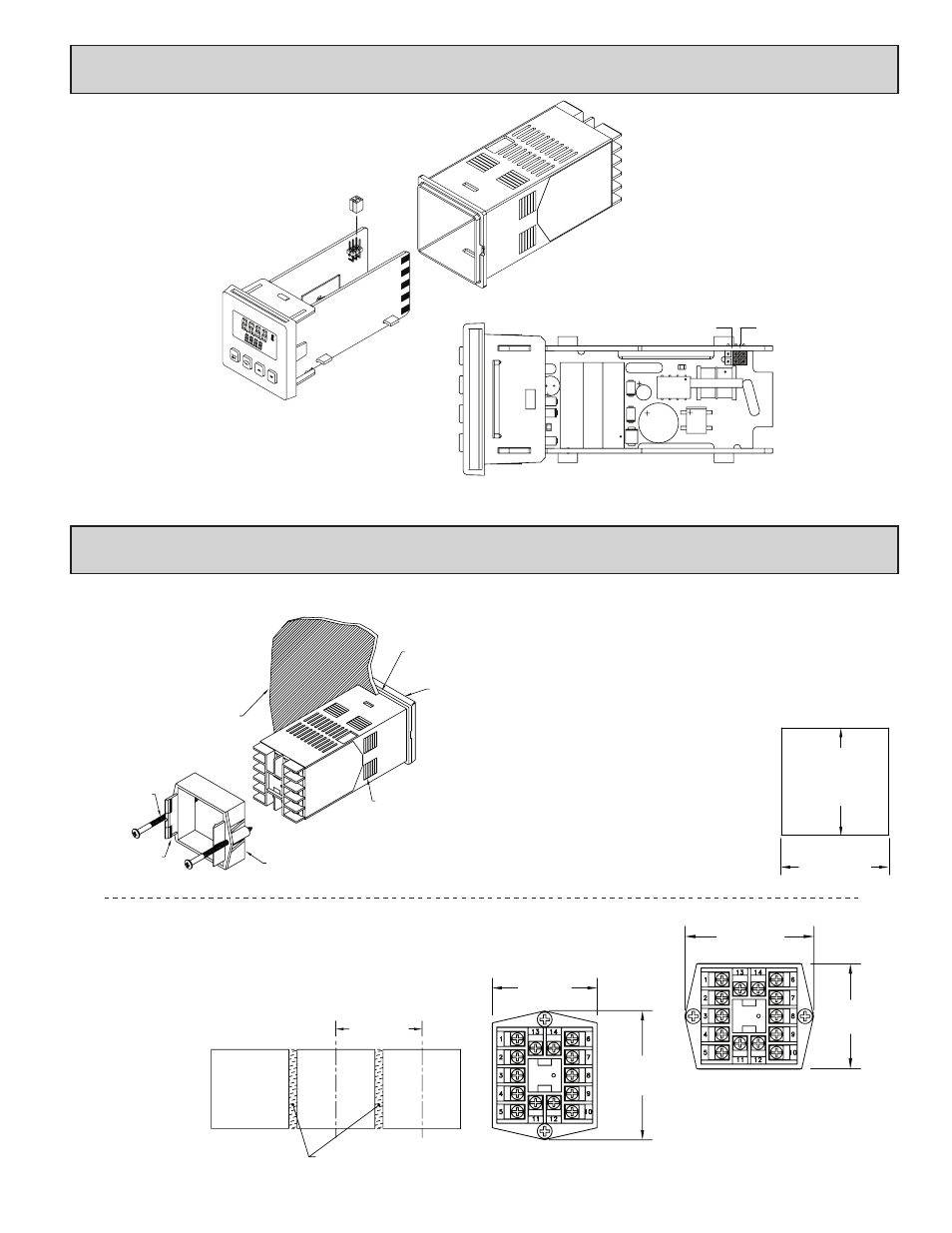
To insure proper operation, the Analog Output jumpers must be set to the same
range selected in programming Module 2-OP. The default jumper setting
is for 20 mA. The default setting in Module 2-OP is 4-20 mA. To
access the jumpers, insert a flat-blade screwdriver between the front
panel and the side case slot. This should disengage the top and
bottom front panel latches from the case grooves. Pull the
front panel assembly with the controller boards out of
the case. The jumpers are located inside the
controller on the left board along the back
top section.
20mA (Both jumpers toward
the rear of the unit)
10V (Both jumpers toward
the front of the unit)
VIEW FROM TOP OF UNIT
02
F1
RDY
A2
01
A1
°
%PW
MAN
%
YORK
, PA
. M
ADE
IN U
.S.A.
RED LION C
ONTROLS
2.0 i
nStAlling
the
C
ontroller
Instructions:
1. Prepare the panel cutout to the proper dimensions.
2. Remove the panel latch from the controller. Discard the cardboard sleeve.
3. Carefully remove the center section of the panel gasket and discard. Slide the
panel gasket over the rear of the controller, seating it against the lip at the
front of the case.
4. Insert the controller into the panel cutout. While holding the controller in
place, push the panel latch over the rear of the controller, engaging the tabs
of the panel latch in the farthest forward slot possible.
5. To achieve a proper seal, tighten the panel latch
screws evenly until the controller is snug in the
panel, torquing the screws to approximately 7
in-lb (79 N-cm). Overtightening can result in
distortion of the controller, and reduce the
effectiveness of the seal.
Note: The installation location of the controller is
important. Be sure to keep it away from heat
sources (ovens, furnaces, etc.) and away from
direct contact with caustic vapors, oils, steam, or
any other process by-products in which exposure
may affect proper operation.
-0.0
+0.6
-0.000
+0.024
-0.0
+0.6
-0.000
+0.024
(45 )
1.772
(45 )
1.772
14
13
6
7
8
10
9
LATCHING
BEZEL
LATCHING
PANEL LATCH
PANEL
MOUNTING
SCREW
TABS
SLOTS
PANEL
PANEL GASKET
Multiple Controller Stacking
The controller is designed to allow for close spacing of multiple controllers
in applications that do not require protection to NEMA 4X. Controllers can be
stacked either horizontally or vertically. For vertical stacking, install the panel
latch with the screws to the sides of the controller. For horizontal stacking, the
panel latch screws should be at the top and bottom of the controller. The
minimum spacing from centerline to centerline of controllers is 1.96" (49.8
mm). This spacing is the
same for vertical or
horizontal stacking.
Note: When stacking
controllers, provide
adequate panel
ventilation to ensure
that the maximum
operating temperature
range is not exceeded.
1.96 (49.8)
MIN
STANDARD
PANEL
CUT-OUT
IF NEMA 4 IS NOT REQUIRED,
THIS PANEL MATERIAL MAY BE REMOVED.
2.39 (60.7)
MAX.
1.96 (49.8)
MAX.
2.39 (60.7)
1.96 (49.8)
MAX
MAX
The T16 and P16 controllers meet NEMA 4X/IP65 requirements for indoor
use to provide a watertight seal in steel panels with a minimum thickness of
0.09", or aluminum panels with a
minimum thickness of 0.12". The
controllers are designed to be
mounted into an enclosed panel.
The bezel assembly must be in
place during installation of
the controller.