1 module 1 - i, P16 o, 1 n – Red Lion P16 User Manual
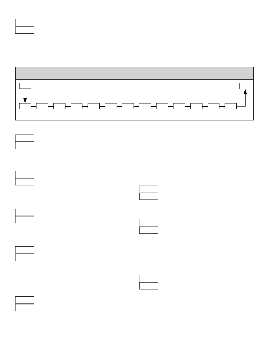
Page 12: I1, F1in, Type dcpt pct rnd fltr dsp1 inp1, Sphi, F1in inpt, Dsp2 inp2, Nput
12
7.1 module 1 - i
nput
p
ArAmeterS
(
1-IN
) p16 o
nly
tYPE
dCPt
PCt
rnd
FLtr
dSP1
INP1
INPUT
TYPE
PERCENT
SYMBOL
DECIMAL
RESOLUTION
ROUNDING
INCREMENT
INPUT
VALUE 1
DISPLAY
VALUE 1
1-IN
CNFP
SPLO
SETPOINT
LOW LIMIT
SPHI
SETPOINT
HIGH LIMIT
F1 KEY
FUNCTION
F1In
InPt
USER
INPUT
DIGITAL
FILTERING
DISPLAY
VALUE 2
INPUT
VALUE 2
dSP2
INP2
A
A
PARAMETER MENU
INPUT TYPE
PERCENT ANNUNCIATOR
On
Off
This only illuminates the % annunciator. It does not perform any type of
percent function, but is useful in applications that have been scaled in percent.
1
n
ROUNDING INCREMENT
1
to
1
In steps of 1 least significant digit,
regardless of decimal point.
Rounding selections other than 1 cause the process value display to round to
the nearest rounding increment selected. (For example, rounding of 5 causes 122
to round to 120 and 123 to round to 125.) Rounding starts at the least significant
digit of the process value. Setpoint values, Setpoint limits, Alarm values, Input
Scaling values, and Analog Scaling values are not affected by rounding.
1
DISPLAY VALUE SCALING POINT 1
to
Enter the first coordinate Display Value by using the arrow keys.
I1
INPUT VALUE SCALING POINT 1
to
2
mA
to
1
V
For Key-in Method, enter the first coordinate Input Value by using the arrow
keys. To allow the P16 to “learn” the signal, use the Applied Method. For Applied
Method, press L. The ° annunciator is turned on to indicate the applied method.
Adjust the applied signal level externally until the appropriate value appears
under I1. Using either method, press A to store the value for I1. (The
controller can be toggled back to the Key-in Method by pressing L before A.)
DECIMAL RESOLUTION
This selection affects the decimal point placement for the Process value, and
related parameters.
1
F
DIGITAL FILTERING
= least to
= most
The filter is an adaptive digital filter that discriminates between measurement
noise and actual process changes. If the signal is varying too greatly due to
measurement noise, increase the filter value. If the fastest controller response is
needed, decrease the filter value.
F1In
F1 KEY FUNCTION
The controller performs the selected F1 Key Function, when L is pressed
while in the Display Loop. In any other loop or module location, pressing L
will perform an escape to the Display Loop.
No Function: No function is performed.
Auto/Manual Select: This function toggles (momentary action) the controller
between Automatic and Manual Control.
Setpoint 1 or 2 Select: This function toggles (momentary action) the controller
between Setpoint 1 and Setpoint 2.
Reset Alarms: This function can be used to reset one or both of the alarms
when activated (momentary action) The alarm will remain reset until the
alarm condition is cleared and triggered again.
Reset Both Alarms
Setpoint 1 or 2 Select
Reset Alarm 2
2
Auto/Manual Select
nF
Reset Alarm 1
1
No Function
FUNCTION
SELECTION
FUNCTION
SELECTION
Voltage
Current
TYPE
SELECTION
Select the input type that corresponds to the input signal.
SCALING
To scale the controller, two scaling points are necessary. Each scaling point has
a coordinate pair of Display Values and Input Values. It is recommended that the
two scaling points be at the low and high ends of the input signal being measured.
Process value scaling will be linear between and continue past the entered points
to the limits of the input range. (Factory settings example will display 0.0 at 4.00
mA input and display 100.0 at 20.00 mA input.) Reverse acting indication can be
accomplished by reversing the two signal points or the Display value points, but
not both. If both are reversed, forward (normal) acting indication will occur. In
either case, do not reverse the input wires to change the action.
1
2
DISPLAY VALUE SCALING POINT 2
to
Enter the second coordinate Display Value by using the arrow keys.