Red Lion P16 User Manual
Page 23
23
PID Adjustments
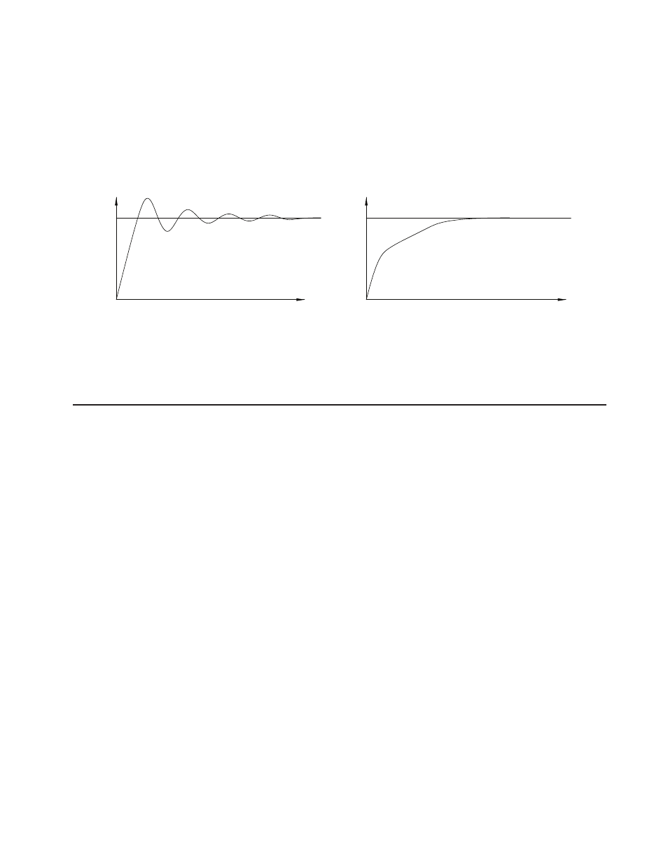
In some applications, it may be necessary to fine tune the Auto-Tune
calculated PID parameters. To do this, a chart recorder or data logging device is
needed to provide a visual means of analyzing the process. Compare the actual
process response to the PID response figures with a step change to the process.
Make changes to the PID parameters in no more than 20% increments from the
starting value and allow the process sufficient time to stabilize before evaluating
the effects of the new parameter settings.
In some unusual cases, the Auto-Tune function may not yield acceptable
control results or induced oscillations may cause system problems. In these
applications, Manual Tuning is an alternative.
TIME
SP
SP
TIME
INPUT
INPUT
OVERSHOOT AND OSCILLATIONS
SLOW RESPONSE
TO DAMPEN RESPONSE:
- USE SETPOINT RAMPING.
- USE OUTPUT POWER LIMITS.
- RE-INVOKE AUTO-TUNE WITH A
HIGHER AUTO-TUNE CODE.
- INCREASE PROPORTIONAL BAND.
- INCREASE INTEGRAL TIME.
- INCREASE DERIVATIVE TIME.
TO QUICKEN RESPONSE:
- INCREASE OR DEFEAT SETPOINT RAMPING.
- EXTEND OUTPUT POWER LIMITS.
- RE-INVOKE AUTO-TUNE WITH A
LOWER AUTO-TUNE CODE.
- DECREASE PROPORTIONAL BAND.
- DECREASE INTEGRAL TIME.
- DECREASE DERIVATIVE TIME.
- CHECK CYCLE TIME.
PROCESS RESPONSE EXTREMES
MANUAL TUNING
A chart recorder or data logging device is necessary to measure the time
between process cycles. This procedure is an alternative to the controller’s Auto-
Tune function. It will not provide acceptable results if system problems exist.
1. Set the Proportional Band () to 10.0% for temperature models (T16) and
100.0% for process models (P16).
2. Set both the Integral Time (In) and Derivative Time () to 0 seconds.
3. Set the Output Dampening Time () in Output Module 2 to 0 seconds.
4. Set the Output Cycle Time [CYCt] in Output Module 2 to no higher than
one-tenth of the process time constant (when applicable).
5. Place the controller in Manual Control Mode nF in the Hidden Loop
and adjust the % Power to drive the process value to the Setpoint value.
Allow the process to stabilize after setting the % Power. Note: nF must be
set to in Parameter Lockouts Module .
6. Place the controller in Automatic () Control Mode nF in the Hidden
Loop. If the process will not stabilize and starts to oscillate, set the
Proportional Band two times higher and go back to Step 5.
7. If the process is stable, decrease Proportional Band setting by two times and
change the Setpoint value a small amount to excite the process. Continue
with this step until the process oscillates in a continuous nature.
8. Fix the Proportional Band to three times the setting that caused the oscillation
in Step 7.
9. Set the Integral Time to two times the period of the oscillation.
10. Set the Derivative Time to 1/8 (0.125) of the Integral Time.
11. Set the Output Dampening Time to 1/40 (0.025) the period of the oscillation.