1 power wiring, 2 input signal wiring, Dp5p input signal wiring – Red Lion DP5T User Manual
Page 8: Dp5d input signal wiring
8
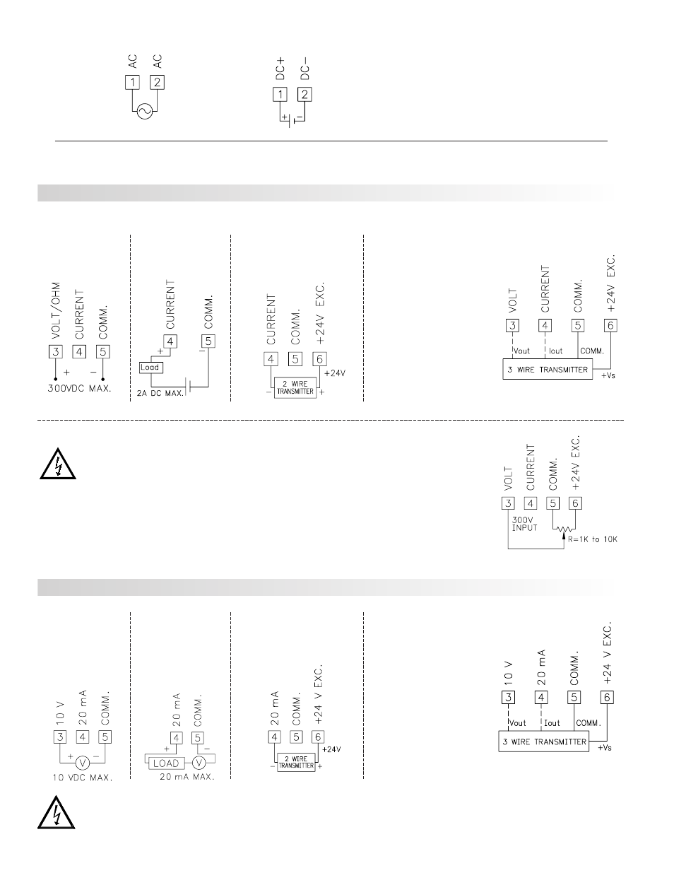
Current Signal
(self powered)
Terminal 4: +ADC
Terminal 5: -ADC
Voltage Signal
(self powered)
Terminal 3: +VDC
Terminal 5: -VDC
Current Signal (2 wire
requiring excitation)
Terminal 4: -ADC
Terminal 6: +ADC
DP5P INPUT SIGNAL WIRING
Current Signal (3 wire
requiring excitation)
Terminal 4: +ADC (signal)
Terminal 5: -ADC (common)
Terminal 6: +Volt supply
Voltage Signal (3 wire
requiring excitation)
Terminal 3: +VDC (signal)
Terminal 5: -VDC (common)
Terminal 6: +Volt supply
CAUTION: Sensor input common is NOT isolated from user input common. In order to preserve the safety of the meter application, the sensor input
common must be suitably isolated from hazardous live earth referenced voltages; or input common must be at protective earth ground potential. If not,
hazardous live voltage may be present at the User Input and User Input Common terminals. Appropriate considerations must then be given to the
potential of the user input common with respect to earth common.
CAUTION: Sensor input common is NOT isolated from user
input common. In order to preserve the safety of the meter
application, the sensor input common must be suitably isolated
from hazardous live earth referenced voltages; or input
common must be at protective earth ground potential. If not,
hazardous live voltage may be present at the User Input and
User Input Common terminals. Appropriate considerations
must then be given to the potential of the user input common
with respect to earth common.
3.1 POWER WIRING
AC Power
Terminal 1: VAC
Terminal 2: VAC
DC Power
Terminal 1: +VDC
Terminal 2: -VDC
Current Signal
(self powered)
Terminal 4: +ADC
Terminal 5: -ADC
Voltage Signal
(self powered)
Terminal 3: +VDC
Terminal 5: -VDC
Current Signal (2 wire
requiring excitation)
Terminal 4: -ADC
Terminal 6: +ADC
Before connecting signal wires, the Input Range Jumper should be verified for proper position.
3.2 INPUT SIGNAL WIRING
Current Signal (3 wire
requiring excitation)
Terminal 4: +ADC (signal)
Terminal 5: -ADC (common)
Terminal 6: +Volt supply
Voltage Signal (3 wire
requiring excitation)
Terminal 3: +VDC (signal)
Terminal 5: -VDC (common)
Terminal 6: +Volt supply
Potentiometer Signal
(3 wire requiring excitation)
Terminal 3: Wiper
Terminal 5: Low end of pot.
Terminal 6: High end of pot.
Input Range Jumper: 300 Volt
Module 1 Input Range: 300 Volt
Note: The Apply signal scaling style
should be used because the signal will
be in volts.
DP5D INPUT SIGNAL WIRING