Iring the, Eter, Dp5p jumper selection – Red Lion DP5T User Manual
Page 7: Dp5t jumper selection, Wiring overview, Emc installation guidelines
7
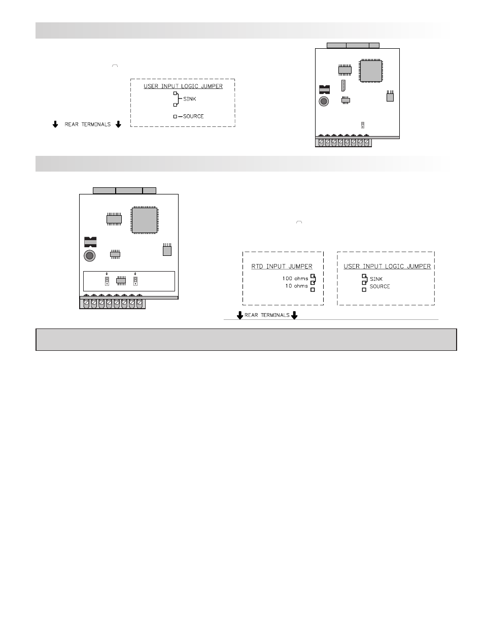
DP5P Jumper Selection
JUMPER SELECTIONS
The
indicates factory setting.
Main
Circuit
Board
USER INPUT
JUMPER
LOCATION
WIRING OVERVIEW
Electrical connections are made via screw-clamp terminals located on the
back of the meter. All conductors should conform to the meter’s voltage and
current ratings. All cabling should conform to appropriate standards of good
installation, local codes and regulations. It is recommended that power supplied
to the meter (DC or AC) be protected by a fuse or circuit breaker.
When wiring the meter, compare the numbers embossed on the back of the
meter case against those shown in wiring drawings for proper wire position.
Strip the wire, leaving approximately 0.3" (7.5 mm) bare lead exposed (stranded
wires should be tinned with solder). Insert the lead under the correct screw-
clamp terminal and tighten until the wire is secure. (Pull wire to verify
tightness.) Each terminal can accept up to one #14 AWG (2.55 mm) wire, two
#18 AWG (1.02 mm), or four #20 AWG (0.61 mm).
EMC INSTALLATION GUIDELINES
Although this meter is designed with a high degree of immunity to Electro-
Magnetic Interference (EMI), proper installation and wiring methods must be
followed to ensure compatibility in each application. The type of the electrical
noise, its source or the method of coupling into the unit may be different for
various installations.Listed below are some EMC guidelines for successful
installation in an industrial environment.
1. The meter should be mounted in a metal enclosure, which is properly
connected to protective earth.
2. Use shielded (screened) cables for all Signal and Control inputs. The shield
(screen) pigtail connection should be made as short as possible. The
connection point for the shield depends somewhat upon the application.
Listed below are the recommended methods of connecting the shield, in order
of their effectiveness.
a. Connect the shield only at the panel where the unit is mounted to earth
ground (protective earth).
b. Connect the shield to earth ground at both ends of the cable, usually when
the noise source frequency is above 1 MHz.
c. Connect the shield to common of the unit and leave the other end of the
shield unconnected and insulated from earth ground.
3. Never run Signal or Control cables in the same conduit or raceway with AC
power lines, conductors feeding motors, solenoids, SCR controls, and
heaters, etc. The cables should be run in metal conduit that is properly
grounded. This is especially useful in applications where cable runs are long
and portable two-way radios are used in close proximity or if the installation
is near a commercial radio transmitter.
4. Signal or Control cables within an enclosure should be routed as far away as
possible from contactors, control relays, transformers, and other noisy
components.
5. In extremely high EMI environments, the use of external EMI suppression
devices, such as ferrite suppression cores, is effective. Install them on Signal
and Control cables as close to the unit as possible. Loop the cable through the
core several times or use multiple cores on each cable for additional
protection. Install line filters on the power input cable to the unit to suppress
power line interference. Install them near the power entry point of the
enclosure. The following EMI suppression devices (or equivalent) are
recommended:
Ferrite Suppression Cores for signal and control cables:
Fair-Rite # 0443167251 (RLC #FCOR0000)
TDK # ZCAT3035-1330A
Steward #28B2029-0A0
Line Filters for input power cables:
Schaffner # FN610-1/07 (RLC #LFIL0000)
Schaffner # FN670-1.8/07
Corcom #1VR3
Note: Reference manufacturer’s instructions when installing a line filter.
6. Long cable runs are more susceptible to EMI pickup than short cable runs.
Therefore, keep cable runs as short as possible.
7. Switching of inductive loads produces high EMI. Use of snubbers across
inductive loads suppresses EMI.
Snubber: RLC#SNUB0000.
3.0 W
IRING THE
M
ETER
DP5T Jumper Selection
Main
Circuit
Board
JUMPER
LOCATION
JUMPER
LOCATION
USER INPUT
RTD
INPUT
JUMPER SELECTIONS
The
indicates factory setting.
RTD Input Jumper
One jumper is used for RTD input ranges. Select the proper range to match the RTD
probe being used. It is not necessary to remove this jumper when not using RTD probes.