Nstalling, Eter, Etting the – Red Lion DP5T User Manual
Page 6: Umpers, Dp5d jumper selection
6
Installation
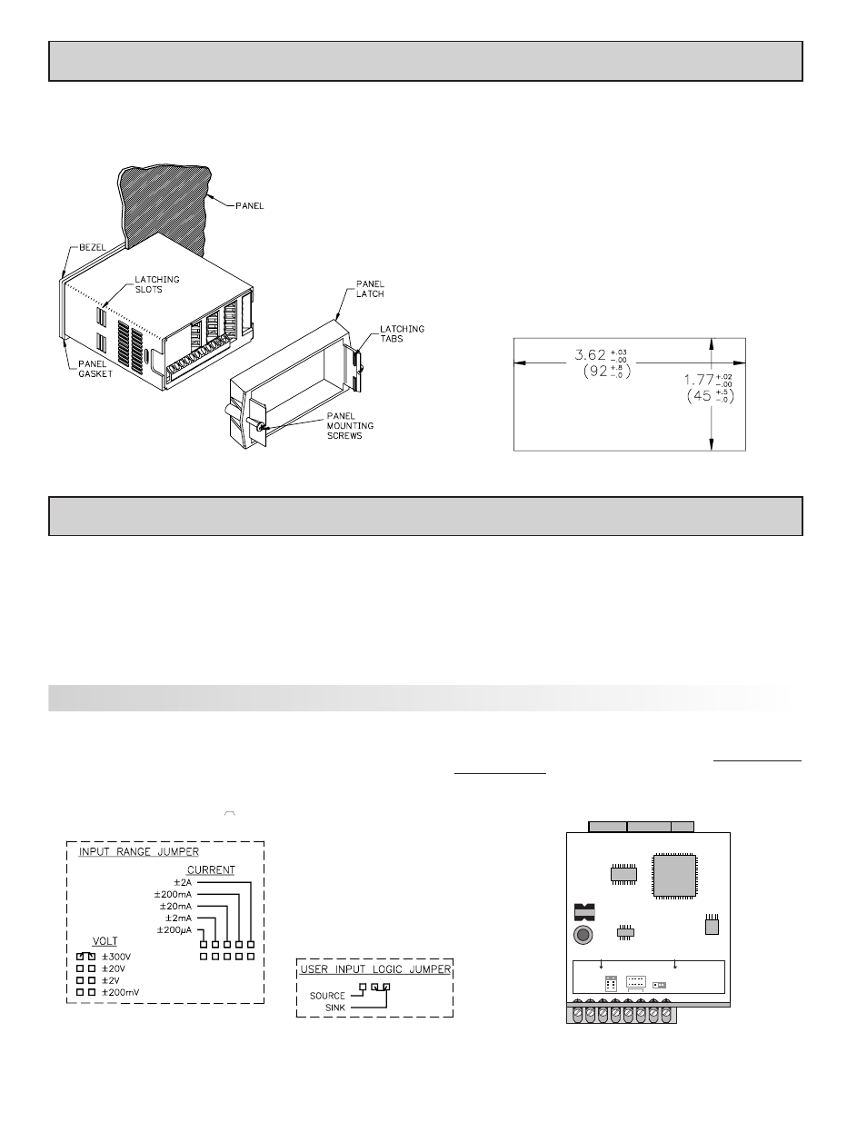
The DP5 meets NEMA 4X/IP65 requirements for indoor use when properly
installed. The unit is intended to be mounted into an enclosed panel. Prepare
the panel cutout to the dimensions shown. Remove the panel latch from the
unit. Slide the panel gasket over the rear
of the unit to the back of the bezel. The
unit should be installed fully
assembled. Insert the
unit into the panel cutout.
While holding the unit in place, push the panel latch over the rear of the unit
so that the tabs of the panel latch engage in the slots on the case. The panel
latch should be engaged in the farthest forward slot possible. To achieve a
proper seal, tighten the latch screws evenly until the unit is snug in the panel
(Torque to approximately 7 in-lbs [79N-cm]). Do not over-tighten the screws.
Installation Environment
The unit should be installed in a location that does not exceed the maximum
operating temperature and provides good air circulation. Placing the unit near
devices that generate excessive heat should be avoided.
The bezel should be cleaned only with a soft cloth and neutral soap product.
Do NOT use solvents. Continuous exposure to direct sunlight may accelerate
the aging process of the bezel.
Do not use tools of any kind (screwdrivers, pens, pencils, etc.) to operate
the keypad of the unit.
PANEL CUT-OUT
1.0 I
NSTALLING
T
HE
M
ETER
2.0 S
ETTING THE
J
UMPERS
The meter can have up to two jumpers that must be checked and / or changed
prior to applying power. The two jumpers are: Input Range and User Input
Logic. The following Jumper Selection Figures show an enlargement of the
jumper area.
To access the jumpers, remove the meter base from the case by firmly
squeezing and pulling back on the side rear finger tabs. This should lower the
latch below the case slot (which is located just in front of the finger tabs). It is
recommended to release the latch on one side, then start the other side latch.
User Input Logic Jumper
This jumper selects the logic state of the user input. If the user input is not
used, it is not necessary to check or move this jumper.
DP5D Jumper Selection
Main
Circuit
Board
JUMPER LOCATIONS
CURRENT
USER INPUT
VOLT/
OHM
JUMPER SELECTIONS
The
indicates factory setting.
Input Range Jumper
One jumper is used for voltage or current input ranges. Select the proper
input range high enough to avoid input signal overload. Only one jumper is
allowed in this area. Do not have a jumper in both the voltage and current
ranges at the same time. Avoid placing the jumper across two ranges.